Introduction to Photoelectric Sensor Encapsulation
Photoelectric sensors are critical components in industrial automation, requiring precise encapsulation to protect sensitive electronics from moisture, dust, and mechanical stress. The encapsulation machine for these sensors integrates advanced dispensing, curing, and inspection modules to ensure high yield and reliability. This article provides a detailed visual guide and technical breakdown of the machine’s core subsystems, with emphasis on critical imaging points for engineers.
Core Subsystem 1: Dispensing Module
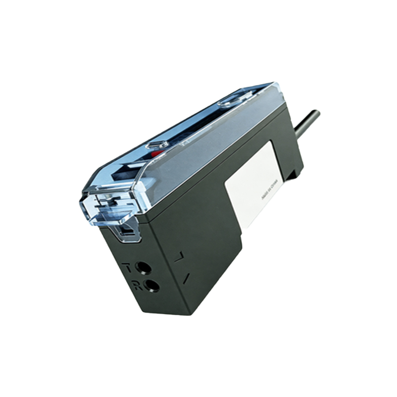
The dispensing module is responsible for applying encapsulant (e.g., epoxy, silicone) around the sensor’s LED and receiver components. High-resolution images capture the precision needle valve, positive displacement pump, and thermal stabilization jacket. Key imaging angles include the needle tip alignment to the sensor pad, and the uniform flow of material without bubbles or voids. Engineers should look for images showing the nozzle’s X/Y/Z adjustment mechanisms and the purge station for clog prevention.
Core Subsystem 2: Curing Oven Unit
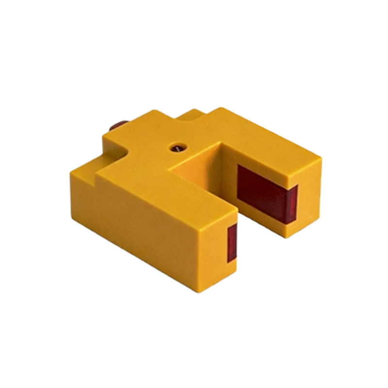
After dispensing, the sensor enters a multi-zone curing oven with infrared (IR) and convection heating. Images should highlight the conveyor belt speed control, temperature sensor array (thermocouples), and exhaust airflow patterns. A cross-section view of the oven chamber illustrating heat distribution and UV curing lamps (if applicable) is essential for process optimization. Visuals showing the cooling station immediately after curing are also crucial to prevent thermal shock.
Core Subsystem 3: Vision Inspection Station
Post-cure, each sensor undergoes automated optical inspection (AOI). Photos of the high-resolution camera (e.g., 5MP or 12MP) with ring lighting, the part handling gripper, and the reject bin are necessary. Emphasize the imaging of the sensor’s lens alignment, encapsulant thickness uniformity, and the absence of cracks or delamination. Engineers benefit from images that display the software interface showing pass/fail criteria, such as pixel count for voids.
Core Subsystem 4: Material Handling and Indexing
The machine’s indexing system uses a rotary table or linear conveyor to move sensor carriers between stations. Images should show the servo-driven indexing mechanism, vacuum pick-and-place heads, and the magazine feeder for empty carriers. Clear photographs of the sensor holding fixture (e.g., spring-loaded clips) and the alignment pins are vital for troubleshooting jams or misalignment. A top-down view of the entire work cell layout aids in understanding material flow.
Pneumatic and Electrical Cabinet Overview
For maintenance, images of the pneumatic manifold, solenoid valves, and electrical cabinet (with PLC, servo drivers, and safety relays) are indispensable. Close-ups of the pressure regulators, filter regulators, and the main power disconnect switch provide context for safety interlocks. A well-labeled diagram of the electrical cabinet’s power distribution and signal termination blocks helps technicians trace faults.
Best Practices for Machine Images
When capturing images for documentation or troubleshooting, use consistent lighting (diffused LED panels) to avoid glare on glossy encapsulants. Include a scale bar or reference object (e.g., a coin) for size context. For moving parts, use a high shutter speed (1/500s or faster) to freeze motion blur. Annotate images with arrows or circles to highlight critical features like sensor alignment markers or nozzle wear areas.
Conclusion
A well-documented image set of the photoelectric sensor encapsulation machine supports engineers in setup, calibration, and diagnostics. By focusing on dispensing accuracy, curing profiles, and inspection criteria, technicians can maintain high process capability (Cpk > 1.67). Always store images in a searchable database with metadata tags for station name, date, and operator comments.