1. Introduction to Photoelectric Sensor Modification
Photoelectric sensors are widely used in industrial automation for object detection, counting, and positioning. However, standard off-the-shelf sensors often fail to meet specific requirements such as extreme environment tolerance, enhanced range, or custom output formats. This article presents a practical modification design to upgrade a common photoelectric sensor for high-precision applications in manufacturing lines.
2. Identifying Modification Needs and Constraints
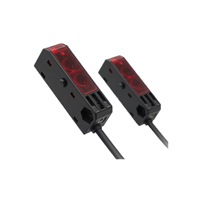
Before starting the design, it is crucial to analyze the existing sensor model, typically a through-beam or retro-reflective type. Key constraints include the sensor's housing size, power supply voltage (e.g., 24V DC), and maximum switching frequency. The goal is to increase detection accuracy to 0.1 mm from the original 1 mm, while maintaining IP67 protection rating. This requires selecting a suitable emitter and receiver pair with narrower beam divergence.
3. Circuit Redesign for Signal Amplification
The core of the modification is the analog front-end circuit. Replace the original phototransistor with a high-speed PIN photodiode (e.g., SFH 213) to achieve faster response. Design a transimpedance amplifier using an operational amplifier like OPA657, which offers low noise and high bandwidth. Add a second-order active low-pass filter with cutoff at 10 kHz to suppress ambient light interference. Finally, integrate a Schmitt trigger to convert the analog signal into a clean digital pulse for the PLC input.
4. Optical System Optimization
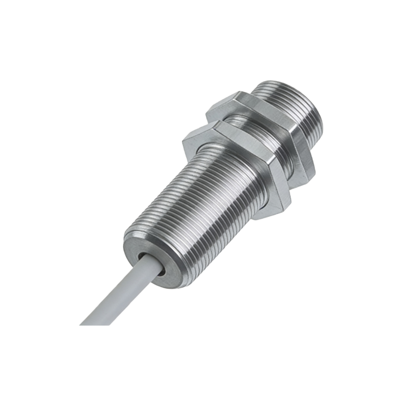
To improve focusing, replace the standard LED with a laser diode module emitting at 650 nm, equipped with a collimating lens. This reduces the beam spot size from 5 mm to 0.2 mm at a 1-meter distance. Use an optical aperture stop and anti-reflective coating on the receiver lens to minimize stray light. Test the alignment using a precision jig to ensure consistent performance across temperature variations from 0 to 50 degrees Celsius.
5. Mechanical Integration and Enclosure Adaptation
The modified sensor must fit within the original housing. Design a 3D-printed adapter bracket for the new laser diode and lens assembly, using a material like ABS for durability. Seal all openings with silicone gaskets to maintain IP67 rating. Add a heat sink for the power amplifier stage if the current consumption exceeds 100 mA. Document the pinout changes for easy reconnection to the existing cable.
6. Calibration and Performance Validation
After assembly, perform calibration using a calibrated micrometer stage. Set the detection threshold to the midpoint of the rising and falling edge of the target. Measure the response time with an oscilloscope: target rise/fall time should be below 10 microseconds. Validate the repeatability over 10,000 cycles using a metal target moving at 5 m/s. Record the maximum operating distance: expected to be 2 meters for a 10 mm target.
7. Conclusion and Application Notes
This modification design successfully transforms a standard photoelectric sensor into a high-precision instrument suitable for pick-and-place systems and quality inspection. Future work includes adding an I2C interface for adjustable sensitivity via a microcontroller. Always follow ESD precautions during assembly and verify compliance with relevant industrial safety standards before deployment.