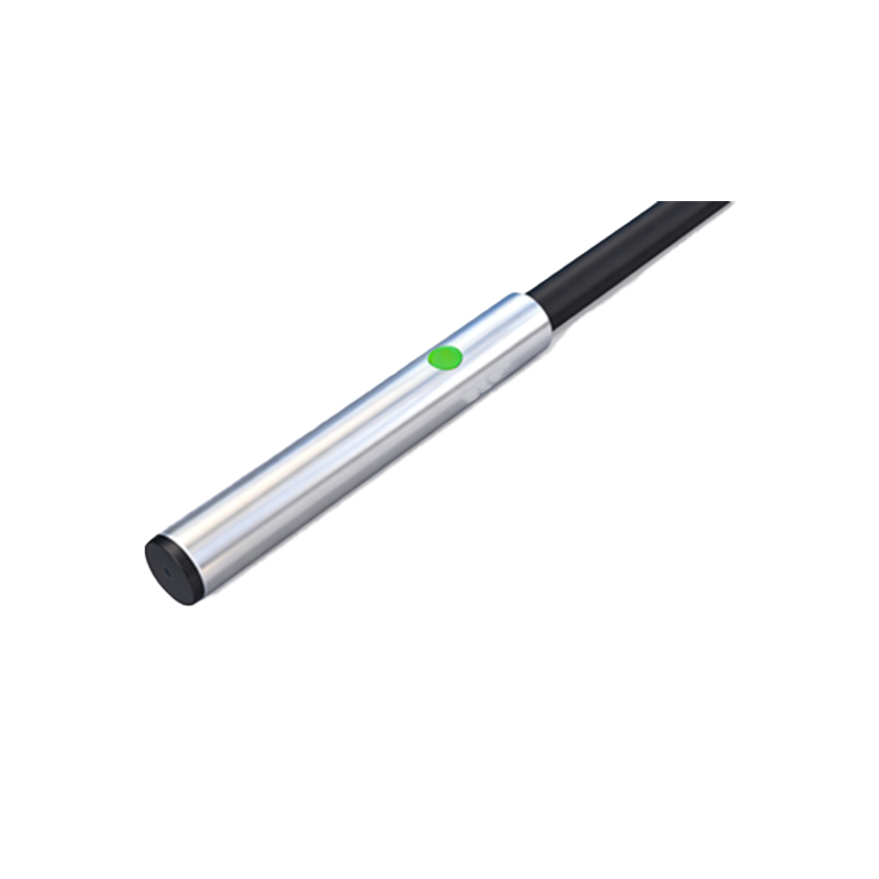
In industrial automation and control systems, proximity sensors play a critical role in detecting the presence or absence of objects without physical contact. Proper electrical marking of these sensors is essential for ensuring safety, facilitating maintenance, and complying with international standards. This article delves into the principles, standards, and best practices for electrical marking of proximity sensors.
Electrical marking refers to the identification of terminals, wires, and connections associated with a proximity sensor. This includes labels for power supply, output signals, and grounding points. Clear and consistent marking helps technicians quickly understand the wiring configuration, reducing installation errors and downtime. For instance, a typical three-wire DC proximity sensor may have terminals marked as +V (brown wire for positive supply), 0V (blue wire for negative supply), and OUT (black wire for output signal). In AC sensors, markings might include L (live) and N (neutral).
International standards, such as IEC 60947-5-2 and ISO 13849, provide guidelines for electrical marking to ensure uniformity across devices and regions. These standards specify color codes, symbols, and alphanumeric identifiers. For example, brown is commonly used for positive DC supply, blue for negative DC or neutral AC, and black or white for output signals. Additionally, protective earth connections are marked with the symbol or the letters PE, often with a green-yellow wire. Adhering to these standards not only enhances safety but also supports global compatibility of components.
The importance of accurate electrical marking extends beyond initial installation. During troubleshooting or system modifications, well-marked sensors enable faster diagnostics. Mislabeled or unmarked connections can lead to incorrect wiring, potentially causing sensor failure, equipment damage, or even hazardous situations. In complex machinery with multiple sensors, consistent marking—such as using sequential tags like PS1, PS2—helps organize the control system logically.
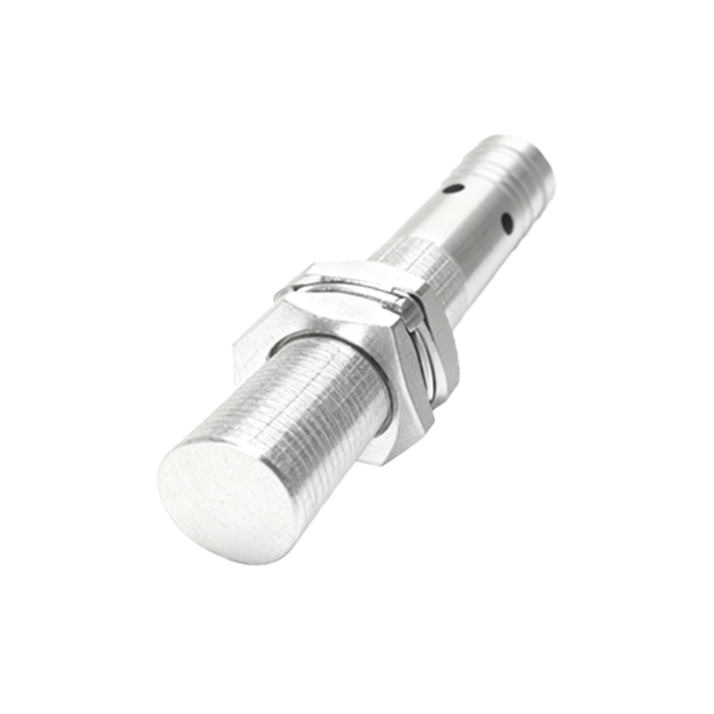
Best practices for electrical marking include using durable, legible labels resistant to environmental factors like oil, dust, and temperature fluctuations. Documentation, such as wiring diagrams and datasheets, should align with the physical markings. Technicians must be trained to recognize standard markings and understand their implications. For instance, a marking of "NC" (normally closed) versus "NO" (normally open) indicates the output state when no target is detected, affecting circuit design.
In summary, electrical marking of proximity sensors is a fundamental aspect of industrial electrical engineering. It bridges the gap between theoretical design and practical implementation, ensuring systems operate reliably and safely. By following established standards and adopting clear marking practices, engineers and technicians can optimize performance and maintainability in automated environments.