Understanding the Basics of Photoelectric Sensor Wiring
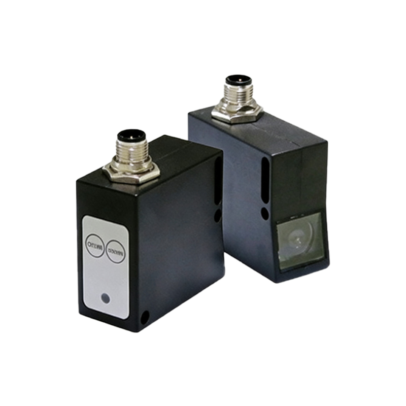
Photoelectric sensors are widely used in industrial automation for object detection, counting, and positioning. Before wiring, always verify the sensor type (diffuse, retro-reflective, or through-beam) and its output configuration (NPN or PNP). Most sensors have a standard 3-wire or 4-wire connection: brown (VCC, typically 10-30 VDC), blue (GND), and black (signal output). For 4-wire sensors, an additional white wire may serve as a second output or test input. Always consult the datasheet for the exact pinout.
Selecting the Correct Power Supply and Load
Ensure the power supply voltage matches the sensor rating, e.g., 24 VDC is common. The sensor’s output current capacity is usually around 100-200 mA, so the connected load (PLC input, relay, or LED) must not exceed this limit. For inductive loads like relays, add a flyback diode across the load to protect the sensor from voltage spikes. Use a regulated power supply to avoid noise interference.
Wiring for NPN (Sinking) Output Sensors
NPN sensors are common in Asian and European systems. Connect the brown wire to +24V, blue wire to 0V (GND). The black output wire connects to the load (e.g., PLC input) and the other side of the load goes to +24V. When the sensor detects an object, the output switches to low (0V), completing the circuit through the load. For multiple sensors, ensure the PLC input is configured for sinking mode.
Wiring for PNP (Sourcing) Output Sensors
PNP sensors are typical in North American applications. Wire the brown to +24V, blue to 0V. The black output connects to the load, with the other load terminal connected to 0V. When triggered, the output goes high (+24V), sourcing current to the load. This configuration is often preferred for compatibility with PLCs configured for sourcing inputs.
Troubleshooting Common Wiring Issues
If the sensor does not respond, check power voltage at the brown-blue terminals using a multimeter. Verify that the load impedance is correct. For NPN sensors, a common mistake is connecting the load to 0V instead of +V. For PNP, ensure the load is not shorted to 0V. Also, inspect for loose connections, polarity reversal, or damage to cables. Use shielded cable for long runs (over 10 meters) to reduce electromagnetic interference.
Best Practices for Industrial Installation
Always route sensor cables separately from high-voltage power cables to prevent noise. Use proper strain relief at connectors. For harsh environments, select sensors with IP67 or higher ratings. Test the wiring with a known good load before finalizing. Document the wiring diagram for future maintenance. Remember to switch off power before making or modifying connections.