Understanding the PF31 Photoelectric Sensor Wiring Basics
The PF31 photoelectric sensor is a widely used industrial component for detecting the presence or absence of objects in automated systems. As an electrical engineer, proper wiring is critical to ensure reliable operation and avoid equipment damage. The sensor typically features three or four wires, depending on the model: brown (positive power supply, usually 10-30V DC), blue (negative power supply or ground), black (normally open output, NPN or PNP type), and sometimes white (normally closed output or alarm). Always consult the manufacturer’s datasheet for exact pin assignments to prevent reverse polarity issues.
Step-by-Step Wiring Procedure for Standard PF31 Models
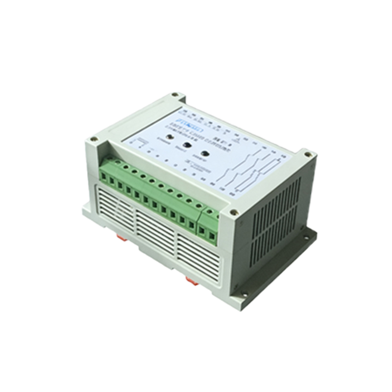
Begin by disconnecting power to the system to eliminate electrical hazards. For a NPN (sinking) output configuration, connect the brown wire to the positive terminal of a DC power supply (e.g., +24V), and the blue wire to the negative terminal (0V or ground). The black output wire should be connected to the input of a PLC or load, with the load’s other side connected to the positive supply. For a PNP (sourcing) output, the black wire connects to the load, and the load’s other side goes to ground. Use shielded cables for long runs to minimize electromagnetic interference, and secure all connections with proper terminal blocks or solder joints.
Troubleshooting Common Wiring Issues
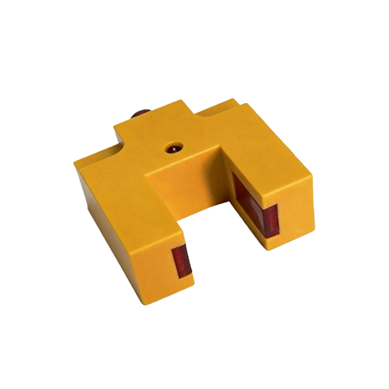
If the sensor fails to detect objects, first verify the power supply voltage with a multimeter—PF31 models require a stable 10-30V DC. Check for loose connections or corrosion at the terminals. For intermittent operation, inspect the cable for breaks or shorts, especially near bending points. When using a PLC, ensure the input module matches the sensor’s output type (NPN vs. PNP). If the sensor remains active when no object is present, adjust the sensitivity potentiometer if available, or confirm the wiring of the normally closed (NC) wire is correct.
Advanced Considerations for Industrial Environments
In harsh environments, such as those with high humidity or dust, use IP67-rated PF31 sensors and seal all connections with dielectric grease or heat-shrink tubing. For systems with long cable distances exceeding 100 meters, consider adding a noise filter or using a twisted-pair cable to maintain signal integrity. Always label wires according to industry color codes (e.g., brown for V+, blue for V-) to simplify future maintenance. Test the sensor by moving an object in front of it and observing the output signal on an oscilloscope for clean switching transitions.
Safety and Best Practices for Final Installation
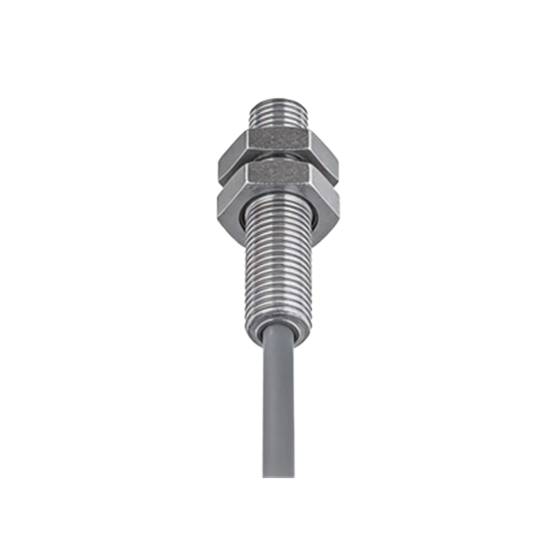
After wiring, conduct a full system test under load to ensure the sensor responds correctly to all targets. Use a fuse or circuit breaker on the power line to protect against overcurrent. Avoid running sensor cables parallel to high-voltage power lines to prevent inductive coupling. Document the wiring diagram and sensor settings in the system manual for future reference. As a final step, secure all cables with cable ties to reduce strain on connectors.