Introduction to Optoelectronic Tachometry
Optoelectronic sensors are widely utilized in industrial environments to measure rotational speed with high precision and reliability. These sensors operate by detecting interruptions or reflections of light beams, which correlate with the rotation of a target object. Common applications include motor speed monitoring, conveyor belt control, and machinery diagnostics. The core advantage of optical methods is their non-contact nature, reducing mechanical wear and enabling high-speed measurements. This article details three primary techniques: reflective, transmissive, and incremental encoding.
Reflective Method Using Photoelectric Sensors
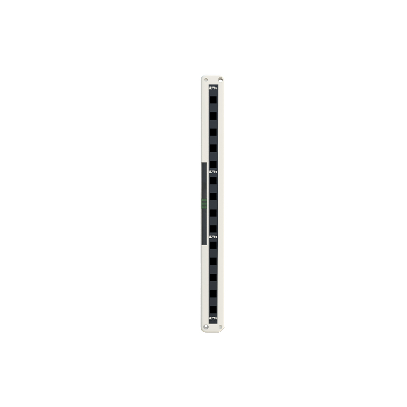
The reflective method employs a photoelectric sensor paired with a reflective marker attached to the rotating shaft. As the shaft rotates, the marker passes the sensor each revolution, causing a light pulse to be reflected back. The sensor’s receiver detects this pulse, converting it into an electrical signal. Frequency measurement of these pulses via a microcontroller or PLC determines the rotational speed. For example, if 60 pulses are counted in 60 seconds, the speed is 60 RPM. Calibration involves adjusting the sensor’s threshold to avoid false triggers from ambient light or surface irregularities. This method is cost-effective but requires precise marker placement.
Transmissive Method with Slotted Disks
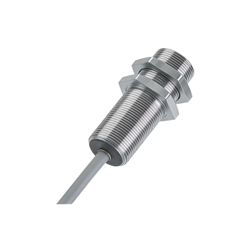
The transmissive method uses a slotted disk attached to the rotating shaft, placed between an emitter and receiver of a photoelectric sensor. The disk has evenly spaced slots or holes; as it rotates, each slot allows light to pass, generating a pulse. The pulse frequency directly relates to rotational speed. For instance, a disk with 100 slots yields 100 pulses per revolution. Calculating speed involves dividing the pulse count over a time interval by the number of slots. This technique excels in high-accuracy applications due to its predictable pulse pattern but demands careful alignment to prevent mechanical vibration errors.
Incremental Encoder Technique
Incremental encoders are advanced optoelectronic devices providing both speed and position feedback. They consist of a rotating disc with alternating transparent and opaque segments, illuminated by an LED. Photodetectors generate quadrature signals (A and B channels), allowing detection of rotation direction and precise speed calculation. Speed is derived from the time interval between successive pulses in a channel. This method offers high resolution (thousands of pulses per revolution) and is immune to dust or oil contamination when sealed. Industrial applications include servo motor control and robotic arm positioning.
Signal Processing and Accuracy Considerations
Accurate speed measurement depends on robust signal processing. Filters eliminate high-frequency noise from electromagnetic interference, while Schmitt triggers sharpen pulse edges for reliable counting. Sampling rates must exceed the Nyquist frequency to avoid aliasing. Environmental factors like ambient light, temperature, and vibration affect sensor performance; using modulated light sources or shielded cables mitigates these issues. For precise calibration, standard tachometers or laser Doppler vibrometers serve as references. Maintenance includes cleaning optical surfaces and checking alignment periodically.
Practical Implementation Example
A typical setup: mount a reflective tape on a motor shaft, position a diffuse reflective photoelectric sensor at 10 cm distance, and connect the sensor output to a PLC high-speed counter. Configure the PLC to count pulses over 1-second intervals. Speed in RPM = (pulse count / 60) * (1 / number of reflective segments). For single segment, RPM equals pulse count per minute. Test with a variable frequency drive to verify linearity. Troubleshoot common issues like partial reflection loss by using contrast-enhanced tape or adjusting mounting angle.