In the realm of precision measurement and industrial automation, laser displacement sensors have become indispensable tools. Their core function is to provide a numerical reading—a distance value—with high accuracy and speed, without physical contact with the target object. But what exactly does this reading represent, and what factors influence its reliability? This article delves into the fundamentals of laser displacement sensor readings, exploring the technology behind the numbers and their practical significance.
At its heart, a laser displacement sensor emits a focused beam of light—typically a visible red laser or a more advanced Class 2 laser—onto a target surface. The sensor then detects the position of the reflected light spot using an optical receiving element, such as a Position Sensitive Detector (PSD) or a CMOS/CCD array. The core principle involves triangulation: the known angle between the emitter and the receiver, combined with the position of the reflected light on the detector, allows the sensor's internal processor to calculate the exact distance to the target. This calculated value is the primary reading, usually output in millimeters or inches.
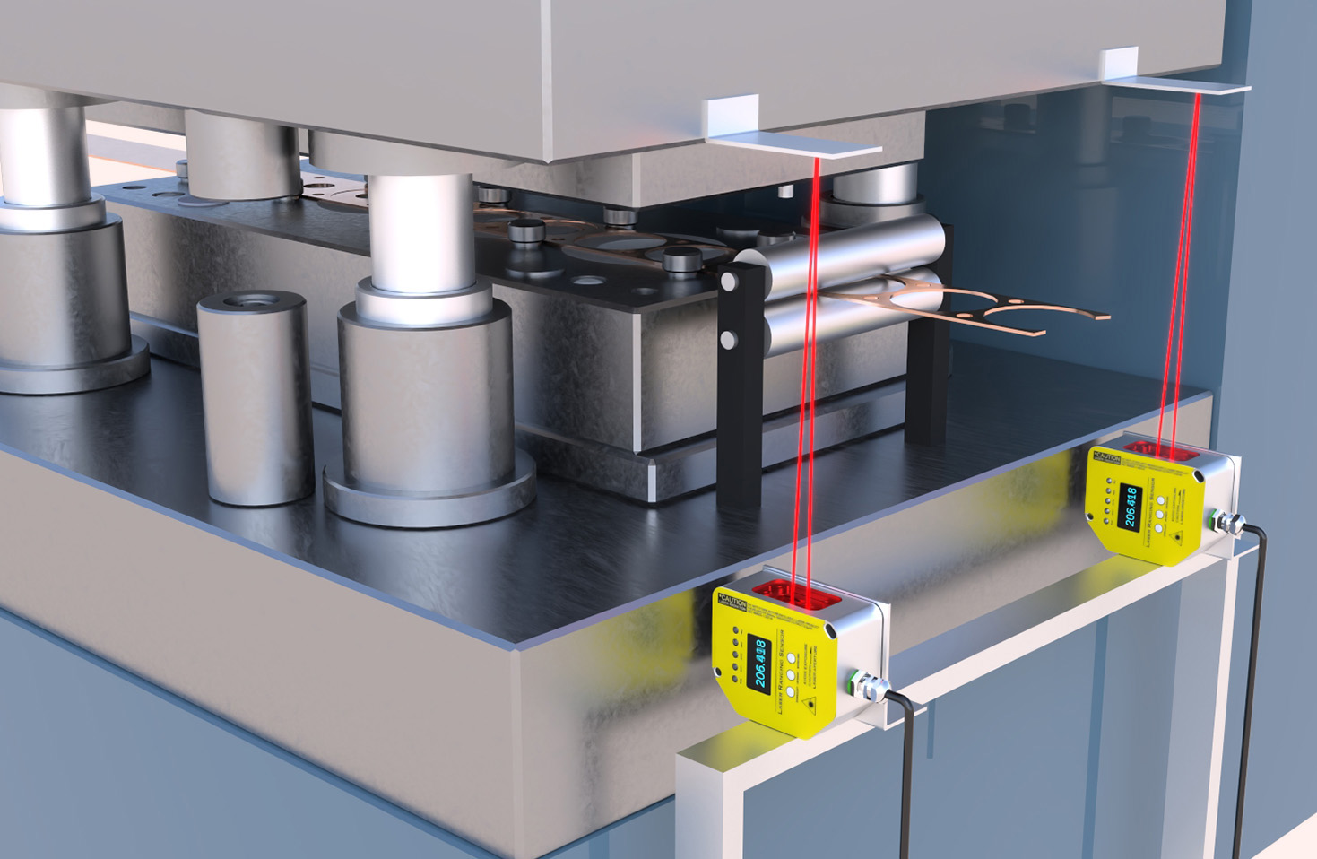
The reading from a laser sensor is not a single, absolute truth but a value contingent on several critical parameters. First and foremost is the sensor's specified measuring range. A sensor designed for a 10mm to 50mm range will provide unreliable or no reading for an object placed 100mm away. Within this defined range, the sensor operates at its optimal performance. Another crucial specification is resolution, which defines the smallest detectable change in distance. A sensor with a 0.1µm resolution can detect minute variations invisible to the human eye, making it suitable for surface profiling or vibration analysis, whereas a 1mm resolution sensor suffices for basic presence detection.
Accuracy and linearity are perhaps the most vital metrics for interpreting readings. Accuracy defines how close the sensor's reading is to the true distance. It is often expressed as a percentage of the full-scale measurement or as a fixed value (e.g., ±0.05% of F.S.). Linearity indicates how consistently the sensor's output deviates from a perfect straight line across its entire measuring range. A high-quality sensor will have excellent linearity, meaning the relationship between the actual distance and the output signal is predictable and can be reliably calibrated. Environmental factors significantly impact these readings. The target's surface characteristics are paramount. A matte, white surface provides ideal, diffuse reflection, yielding a stable and accurate reading. Shiny, mirror-like surfaces cause specular reflection, potentially scattering the beam and leading to measurement errors or loss of signal. Transparent materials like glass or clear plastic can allow the laser to pass through, requiring specialized sensors or surface treatment. Ambient light, especially strong sunlight or other laser sources, can interfere with the detector. Industrial-grade sensors incorporate optical filters and modulated laser light to mitigate this noise. Temperature fluctuations can affect the sensor's electronic components and the wavelength of the laser, potentially causing drift in readings. Many sensors include temperature compensation circuits to stabilize performance.
In practical applications, the reading is rarely used in isolation. It is typically part of a control or monitoring system. For example, in assembly line quality control, the sensor's reading is compared against a preset tolerance window. If the reading indicates a part is too thick or too thin, the system can flag it for rejection. In robotics, the continuous stream of distance readings guides a robotic arm for precise picking and placing. For profile measurement, a sensor mounted on a scanning axis takes thousands of readings per second to build a detailed 3D contour of an object. The output interface is key to utilizing the reading. Analog outputs (4-20mA, 0-10V) provide a continuous voltage or current proportional to the distance, ideal for direct connection to PLCs (Programmable Logic Controllers). Digital interfaces (RS-485, Ethernet/IP, PROFINET) transmit the numerical value directly, often with higher noise immunity and the ability to daisy-chain multiple sensors.
To ensure trustworthy readings, proper installation and calibration are non-negotiable. The sensor must be mounted securely to minimize vibration. The laser beam should be perpendicular to the target surface within the sensor's specified allowable tilt angle to avoid cosine error. Regular calibration against a known reference, such as gauge blocks, verifies long-term accuracy. Understanding the difference between the sensor's reference point (usually the front housing or a marked spot) and the actual beam emission point is also essential for correct offset programming.

In conclusion, a laser displacement sensor reading is a sophisticated data point born from optical triangulation and advanced signal processing. Its value is a function of the sensor's inherent specifications, the target's properties, and the operating environment. By comprehensively understanding these interacting factors—resolution, accuracy, surface type, and environmental robustness—engineers and technicians can select the right sensor, install it correctly, and interpret its readings with confidence. This transforms a simple number into a powerful driver for quality assurance, process optimization, and innovation across manufacturing, electronics, automotive, and research industries.