Understanding the Spray Photoelectric Sensor
Spray photoelectric sensors are widely used in industrial environments for detecting objects in harsh conditions, such as in wash-down areas or where liquids are present. These sensors combine a light emitter and receiver, often using infrared or laser technology, to detect changes in reflected light. Proper wiring is critical for reliable operation and to prevent false triggering or sensor damage. Before beginning, ensure you have the sensor's datasheet, which specifies pin assignments for power, output, and signal lines.
Identifying the Sensor Wiring Terminals
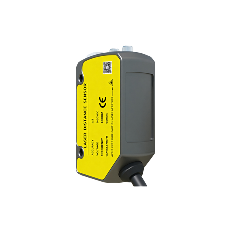
Most spray photoelectric sensors have three or four wires. Standard color coding includes: brown for DC power supply positive (typically 10-30 VDC), blue for ground (0 VDC), and black for the output signal (NPN or PNP). Some models include a white wire for additional functions like sensitivity adjustment or alarm output. Verify the terminal layout on the sensor housing, as miswiring can cause permanent damage. Use a multimeter to confirm voltage levels before connecting.
Connecting Power Supply Lines
Connect the brown wire to the positive terminal of your DC power supply. Ensure the supply voltage matches the sensor's rated range, usually 10-30 VDC. Connect the blue wire to the power supply ground (0 VDC). For safety, use a fuse or circuit breaker in line with the positive supply to protect against short circuits. In high-vibration environments, apply strain relief to the cable near the connection point.
Wiring the Output Signal to a PLC or Controller
The black wire carries the sensor's output signal. If your sensor is NPN (sinking), the output switches to ground when activated. Connect this to a PLC digital input configured as sourcing. For PNP (sourcing) sensors, the output switches to positive voltage; connect to a sinking PLC input. Many modern PLCs support both types, but verify compatibility in your system. Use shielded twisted-pair cable for the signal line to reduce electrical noise interference in industrial settings.
Configuring the Sensor for Spray Environments
Spray sensors often include a sensitivity adjustment potentiometer. After wiring, test the sensor by spraying water or other liquids near the detection zone. Adjust the sensitivity to avoid false triggers caused by liquid droplets. If a white wire exists, it may be used for remote teach-in or alarm output; refer to the manufacturer's manual. Secure all connections in a watertight junction box rated for IP67 or higher to withstand moisture.
Testing and Verifying the Installation
After wiring, power on the system and verify the sensor's LED indicator: solid green usually means power is on and no target is detected, while red indicates an object is present. Use a reflective target to test the sensor's response time. For spray applications, perform a 24-hour continuous test to ensure no intermittent failures occur. Document the wiring diagram and sensitivity settings for future maintenance.