Understanding the Role of Optical Sensors in Profiling Machines
Optical sensors are critical components in profiling machines, used for detecting material edges, surface irregularities, or position feedback. These sensors rely on light beams (often infrared or laser) to trigger outputs. For electrical engineers, proper wiring ensures signal integrity, reduces noise, and prevents false triggers. Common types include through-beam, retro-reflective, and diffuse reflective sensors. Each has distinct wiring requirements based on its output type (NPN, PNP, or analog). Always verify the sensor’s datasheet before starting.
Selecting the Correct Cable and Connector Type
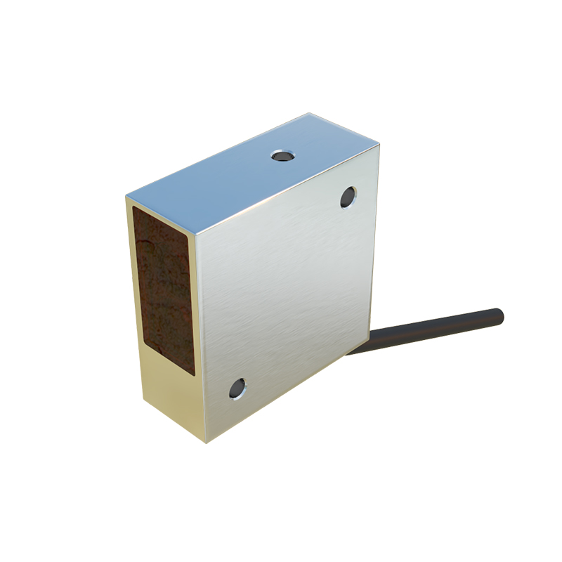
Most industrial optical sensors use M8 or M12 connectors with 3 to 5 pins. For profiling machines, shielded twisted-pair cables are recommended to minimize electromagnetic interference from nearby motors or drives. Pre-wired sensors often simplify installation, but if field wiring is required, use a cable with a minimum AWG 22 rating. Ensure the cable jacket is rated for oil and abrasion resistance, common in machining environments. Color codes typically follow IEC standards: brown for V+, blue for V-, black for output, and white for optional functions like teach-in.
Power Supply Connections: Avoiding Voltage Drops
Optical sensors require a stable DC power supply, usually 10-30 VDC. Connect the brown wire to the positive terminal (V+) and the blue wire to the negative terminal (V-). In profiling machines with long cable runs, calculate voltage drop using Ohm’s law: Vdrop = I × R. For example, a 10-meter cable with 0.1 Ω/m resistance and a 100 mA sensor load gives a 1V drop, which may cause erratic behavior. Use a 24 VDC supply and consider adding a local power distribution block near the sensor to maintain voltage.
Wiring Output Signals: NPN vs. PNP Configuration
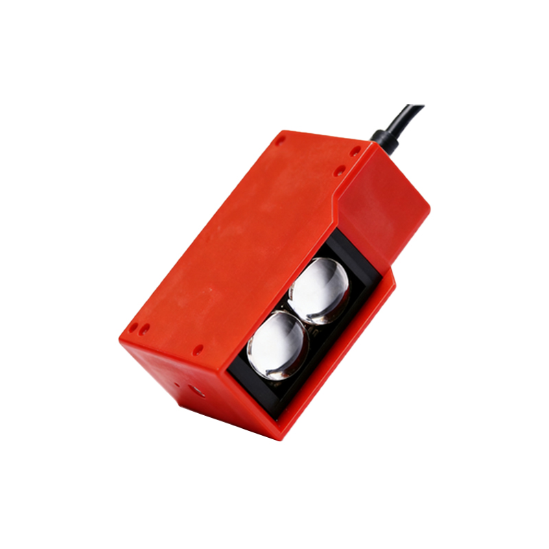
The black wire carries the output signal. For NPN (sinking) sensors, the output connects to 0V (blue) when activated, so you should wire the load between V+ and the output. For PNP (sourcing) sensors, the output connects to V+ when activated, so wire the load between the output and 0V. Many profiling machines use PNP sensors for compatibility with PLC inputs. Always check the PLC input module type. If the sensor has a white wire for a teach-in function, ground it (to V-) for normal operation or apply a brief pulse to set sensitivity.
Grounding and Shielding for Noise Immunity
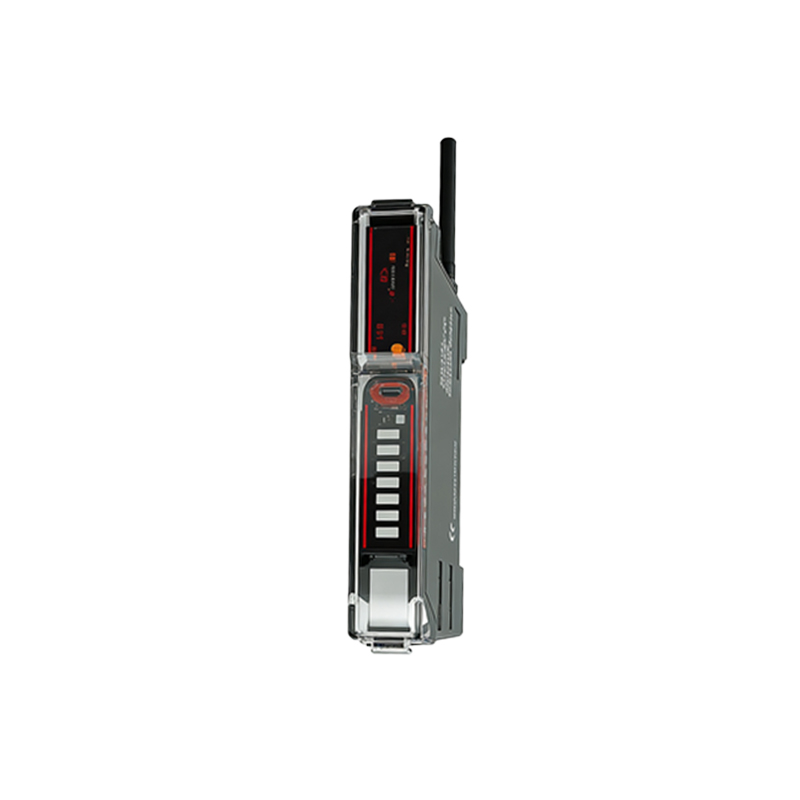
In profiling machines, high-frequency noise from servo drives can corrupt sensor signals. Connect the cable shield to earth ground at the PLC or controller end only, not at the sensor end, to avoid ground loops. Use a ferrite bead on the power cable near the sensor if noise persists. For analog output sensors (e.g., 0-10V or 4-20 mA), ensure the shield is terminated with a drain wire and connected to a clean ground. Avoid running sensor cables parallel to power cables; maintain at least 15 cm separation.
Testing and Troubleshooting Wiring Connections
After wiring, perform a continuity check with a multimeter before powering up. Verify voltage at the sensor: between V+ and V-, it should be within the rated range. With the sensor triggered (e.g., by placing an object in the beam), measure voltage on the output wire relative to V-: for PNP, it should be near V+; for NPN, near 0V. If readings are abnormal, check for loose terminals, reverse polarity, or damaged cable. Use a signal injector to simulate an object for testing without physical movement.
Safety Considerations During Installation
Always lock out/tag out the profiling machine before accessing wiring. Optical sensors may use Class 1 lasers (eye hazard); avoid direct beam exposure. For sensors in hazardous areas (e.g., with cutting fluids), use IP67-rated connectors and seal unused ports. If the sensor is part of a safety circuit (e.g., light curtain), follow specific wiring standards like IEC 61496 to ensure fail-safe operation, including redundant outputs and monitored grounding.