Understanding the Basic Principles and Types
Photoelectric sensors are essential components in industrial automation, detecting objects through light emission and reception. To effectively differentiate between functional and faulty units, engineers must first understand the three primary types: through-beam, retro-reflective, and diffuse sensors. Each type operates on distinct optical principles, affecting how failures manifest. For example, through-beam sensors have separate emitter and receiver, making misalignment a common issue. Retro-reflective sensors rely on a reflector, and diffuse sensors detect scattered light from the target itself. Mastery of these basics is crucial for accurate diagnosis.
Visual Inspection and Physical Checks
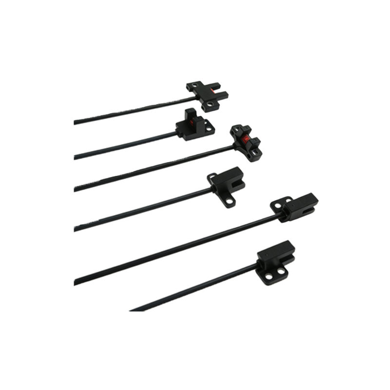
Before any electrical testing, perform a thorough visual inspection. Look for cracks, corrosion, or damage on the sensor housing, lens, and cable. Pay special attention to the optical surface—dirt, oil, or scratches can severely degrade performance. Check the LED indicator: a steady green or orange light typically signals normal operation, while a red or flashing light may indicate a fault. Also, verify that the mounting bracket is secure and that the sensor is properly aligned with the target or reflector. Physical damage often leads to intermittent failures.
Testing Output Signals with a Multimeter
Use a digital multimeter to check the sensor's output signal. For DC sensors (NPN or PNP), set the multimeter to DC voltage mode. Connect the black probe to ground and the red probe to the output wire. When the sensor is triggered (e.g., by placing an object in front of it), the voltage should switch between near 0V and the supply voltage (e.g., 24V). A slow or incomplete transition indicates a failing sensor. For AC sensors, measure the output current; a healthy sensor should rapidly switch states. If the output remains constant regardless of the target, the sensor is likely dead.
Evaluating Response Time and Range
A good photoelectric sensor should have a stable and predictable response time, typically in milliseconds. Use an oscilloscope to observe the signal waveform when a target passes through the sensing area. A clean, sharp square wave indicates proper function. Also, test the sensing range by moving a standard target (e.g., a white card) from the maximum distance to the sensor. If the detection distance is significantly shorter than the datasheet specification, the sensor may have a degraded emitter or dirty optics. Compare results with a known good sensor.
Environmental Factors and Interference Check
Photoelectric sensors are sensitive to ambient light, dust, and electromagnetic interference (EMI). Test the sensor in its actual working environment. Shine a bright flashlight near the sensor; if the output changes falsely, the sensor has poor ambient light rejection. Use a spectrum analyzer or simple AM radio to detect excessive EMI from nearby motors or drives, which can cause false triggering. Additionally, check for condensation on the lens, which can cause erratic behavior. A reliable sensor should maintain stable operation under typical industrial conditions.