Understanding the Small Square Photoelectric Sensor
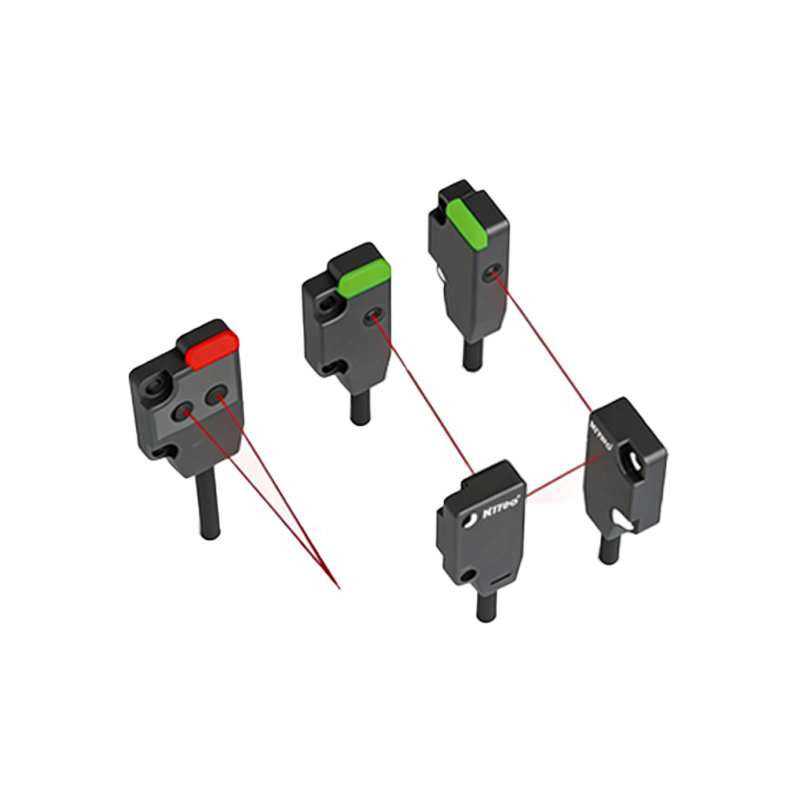
A small square photoelectric sensor is a compact detection device widely used in automated industrial systems. It emits a light beam, typically infrared or visible red, to detect the presence or absence of objects without physical contact. Common types include through-beam, retro-reflective, and diffuse reflective sensors. Before wiring, identify your sensor's output type, such as NPN (sinking) or PNP (sourcing), and its supply voltage, typically 10-30 VDC.
Gathering Necessary Tools and Safety Precautions
To ensure a safe and efficient wiring process, gather a multimeter, a small flat-head screwdriver, wire strippers, and a compatible power supply. Always disconnect power before handling any connections. Verify the sensor's datasheet for pin assignments, as color codes vary by manufacturer. Use cables with appropriate gauge, typically 22-18 AWG, and ensure proper insulation to prevent short circuits in harsh industrial environments.
Identifying Sensor Wire Colors and Functions
Most small square photoelectric sensors follow standard color coding. The brown wire is typically for positive voltage (V+), blue for ground (0V or V-), and black or white for the output signal. Additional wires, such as a pink or gray wire, may indicate a test input or alarm output. Confirm these assignments with the sensor's manual, as some models invert the function of black and white wires.
Wiring an NPN (Sinking) Sensor
For an NPN sensor, the output sinks current to ground when activated. Connect the brown wire to +24 VDC, the blue wire to 0 VDC (common ground), and the black wire to the load (e.g., a PLC input module). The load must be connected between the black wire and the positive power supply. Use a multimeter to verify voltage: when the sensor detects an object, the output voltage drops to near 0 V.
Wiring a PNP (Sourcing) Sensor
A PNP sensor sources current from the positive supply when activated. Wire the brown lead to +24 VDC, blue to 0 VDC, and black to the load, which connects to ground. The load is placed between the black wire and negative supply. Test with a multimeter: the output voltage should rise to near +24 V when detection occurs. Ensure the load's voltage rating matches the sensor's output.
Connecting to a PLC or Controller
Match the sensor output type to your PLC input module. NPN sensors require a sourcing input module that accepts sinking signals, while PNP sensors need a sinking input module. Use shielded twisted-pair cables for long distances to minimize electromagnetic interference. Connect the shield to ground at one end only. Program the PLC to filter noise and set appropriate debounce times for reliable detection.
Troubleshooting Common Wiring Issues
If the sensor fails to operate, first check power supply voltage. Use a multimeter to ensure +24 VDC is present between brown and blue wires. Verify load connections: a miswired NPN output to a PNP input will cause no signal. Test with a known good sensor or substitute a different output type. Clean the sensor lens and align it properly for diffuse or retro-reflective models. Check for loose terminals or damaged cables.
Final Verification and System Integration
After wiring, power the system and test the sensor with a target object. Observe the indicator LED on the sensor: it should illuminate when detection occurs. Use a multimeter to confirm output voltage transitions. Record wiring details for future maintenance. Integrate the sensor into your automation system by configuring parameters like sensitivity and response time. Document the setup for compliance with industrial safety standards.