2026-06-02
Tech Hub
By 创始人
Understanding the 630k Printer Photoelectric Sensor: A Technical Overview for Electrical Engineers
Introduction to Photoelectric Sensors in 630k Printers
Photoelectric sensors are critical components in modern industrial printers, particularly in the 630k series, where they ensure precise media detection, position control, and error prevention. These sensors operate by emitting a beam of light and detecting changes in reflection or interruption caused by paper or other materials. For electrical engineers, understanding the working principles, specifications, and integration of these sensors is essential for maintenance, troubleshooting, and system optimization. The 630k printer typically uses a reflective type photoelectric sensor, which offers reliable performance in dusty or variable lighting conditions common in printing environments.
Operational Principles and Signal Processing
The 630k printer photoelectric sensor utilizes an infrared LED emitter and a phototransistor receiver. When media passes between the emitter and receiver, the light path is blocked or reflected, generating a change in output voltage. This analog signal is then processed by the printer’s control board, converting it into a digital trigger for paper feed, alignment, or jam detection. Key parameters include response time (typically under 1 ms), detection range (5–15 mm), and wavelength (940 nm). Engineers must ensure proper alignment and shielding to avoid false triggers from ambient light or dust accumulation.
Common Failure Modes and Diagnostic Techniques
In field applications, the 630k photoelectric sensor may experience failures due to contamination, misalignment, or component aging. Symptoms include erratic paper feeding, frequent jams, or no media detection. Diagnostics involve measuring output voltage with a multimeter under normal and blocked conditions, checking for clean lens surfaces, and verifying the supply voltage (usually 5V DC). A common fix is recalibrating the sensor sensitivity via the printer’s service menu or adjusting the mounting bracket. For persistent issues, replacing the sensor module is recommended, with careful attention to compatibility and wiring polarity.
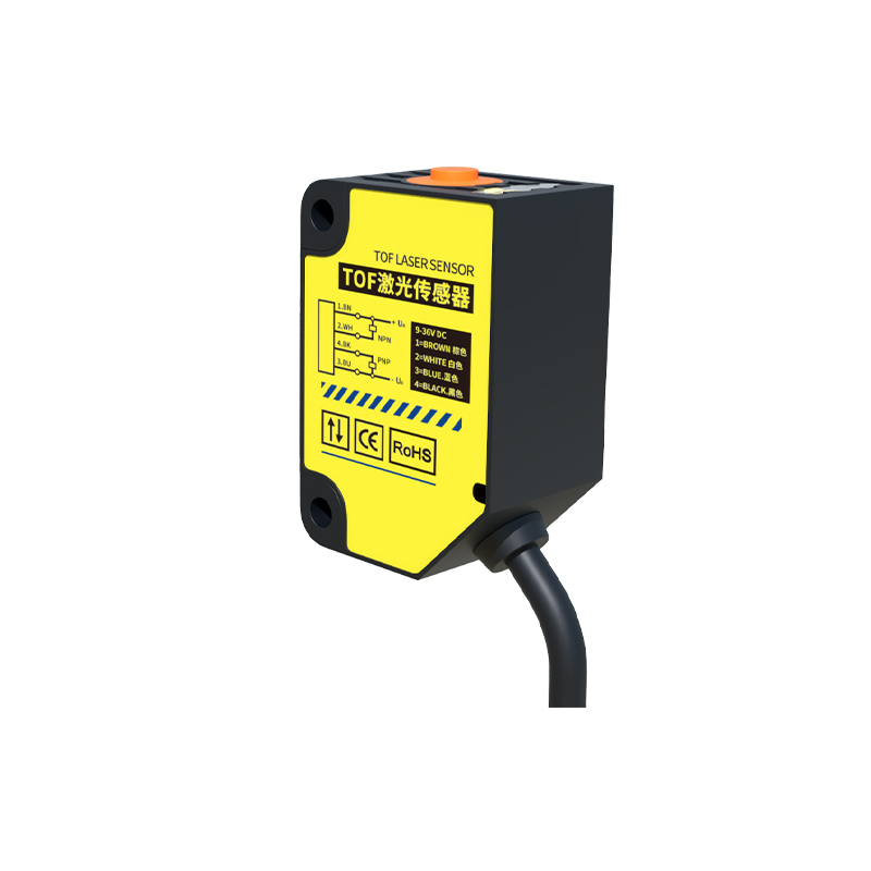
Integration with Printer Control Systems
The sensor interfaces with the mainboard through a 3-pin connector (VCC, GND, Signal). Electrical engineers should note that the signal line is often pulled high internally, and the sensor outputs a low signal when media is detected. Proper grounding and decoupling capacitors near the sensor can reduce noise from motor drives or power supplies. In advanced configurations, multiple sensors may be used for duplex printing or multi-tray systems, requiring multiplexing or dedicated microcontroller inputs. Firmware adjustments may also be necessary to set debounce timers and threshold levels for reliable operation.
Maintenance Best Practices and Upgrades
To extend the lifespan of the 630k photoelectric sensor, regular cleaning with isopropyl alcohol and a lint-free cloth is advised. Engineers should inspect the cable insulation for wear and ensure the sensor is not exposed to excessive vibration or heat. Upgrades to industrial-grade sensors with higher IP ratings (e.g., IP67) can improve durability in harsh environments. Additionally, using sensors with adjustable sensitivity or digital outputs (e.g., I2C) can simplify integration with modern controllers. Always consult the printer’s technical manual for specific electrical ratings and mounting tolerances.