In the realm of industrial automation, robotics, and consumer electronics, proximity sensors are indispensable components. They detect the presence or absence of an object within a specified range without physical contact, enabling countless automated processes. However, a critical aspect often overlooked in system design is the concept of "proximity sensor load." This term does not refer to the physical weight a sensor can bear, but to the electrical load its output is designed to drive. Properly managing this load is paramount for ensuring reliability, longevity, and accurate operation.
At its core, the output stage of a proximity sensor is an electronic switch. This switch, whether solid-state (like a transistor) or electromechanical (like a relay), must connect to and control another device in the circuit, known as the "load." Common loads include programmable logic controller (PLC) input modules, relay coils, solenoid valves, indicator lamps, or small motors. The sensor's specifications define its maximum load capacity, typically expressed in terms of current (amperes, A), voltage (volts, V), and sometimes power (watts, W). Exceeding these ratings is a primary cause of premature sensor failure.
There are two primary output types, each with distinct load considerations. The first is the solid-state output, commonly a transistor-transistor logic (TTL) or a field-effect transistor (FET) circuit. These outputs are fast, have no moving parts, and are resistant to vibration. They are typically used for low-power DC loads. A crucial specification here is the maximum continuous current, often ranging from 20mA to 500mA. Connecting a load that draws more current than this rating will overheat and destroy the internal transistor. Furthermore, with DC sensors, attention must be paid to polarity (sourcing vs. sinking) and the need for protective components like flyback diodes when driving inductive loads such as relay coils. Without a diode, the voltage spike generated when the coil de-energizes can easily damage the sensor's output.
The second type is the relay contact output. Here, the sensor activates a small internal electromagnetic relay whose physical contacts close to complete the circuit. Relay outputs can typically handle higher currents (e.g., 2A to 5A) and can switch both AC and DC loads. The load consideration for relays involves both the current rating and the nature of the load. Inductive loads (motors, solenoids) are harder to switch off than resistive loads (lamps, heaters) due to arcing at the contacts, which leads to wear. For highly inductive loads, derating—using the relay at a fraction of its maximum rating—is often necessary for a reliable service life.
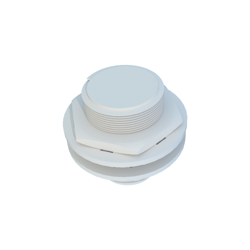
A common and costly mistake is directly connecting a proximity sensor to a device that exceeds its load capacity. For instance, a small 100mA sensor cannot directly power a solenoid valve that requires 1A. The solution is to use the sensor to drive an intermediate device capable of handling the larger load. The standard practice is to connect the sensor output to the coil of a larger, suitably rated power relay or a solid-state relay (SSR). The sensor safely switches the low-current relay coil, and the relay's heavy-duty contacts then switch the high-current load. This isolates the sensitive sensor electronics from the power circuit's demands and potential electrical noise.
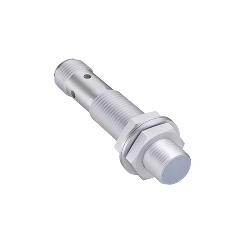
Electrical noise and inrush current are two other load-related challenges. Industrial environments are rich in electromagnetic interference from motors, welders, and other equipment. This noise can cause false triggering of sensitive sensor outputs. Proper wiring practices—using shielded cables, keeping signal wires away from power lines, and employing noise filters—are essential. Inrush current, the momentary surge when a device like a lamp or motor is first energized, can be many times higher than the steady-state operating current. A sensor or relay contact rated for 2A continuous current might be damaged by a 15A inrush spike. Specifying components with an appropriate inrush current rating or using slow-blow fuses and soft-start circuits mitigates this risk.
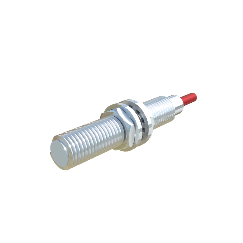
In conclusion, treating a proximity sensor as a simple on/off switch is an oversimplification. Its performance is intrinsically tied to the electrical characteristics of the load it controls. System designers and maintenance technicians must rigorously consult sensor datasheets, understand the difference between output types, calculate the real-world load demands—including peak inrush currents—and implement protective interfacing when necessary. By giving due consideration to proximity sensor load, engineers can build robust, fault-tolerant systems that maximize uptime and minimize costly replacements, ensuring that these silent sentinels of automation perform their duty flawlessly for years to come.