1. Overview of Slot-Type Photoelectric Sensors
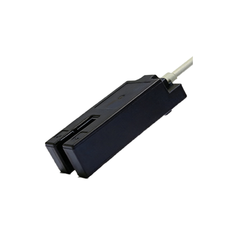
Slot-type photoelectric sensors, also known as through-beam or fork sensors, are widely used in industrial automation for precise object detection. They consist of an emitter and a receiver housed in a single U-shaped body. The emitter sends a modulated light beam across the slot, and the receiver detects interruptions caused by passing objects. This design ensures high accuracy, fast response, and immunity to ambient light interference. Understanding their wiring is critical for reliable system integration.
2. Basic Wiring Configuration
Most slot-type sensors feature three or four wires: a power supply line (brown for positive, blue for negative), an output signal line (black for normally open, white for normally closed), and sometimes a load line. The emitter requires a stable DC voltage, typically 10-30V DC. The receiver outputs a digital signal (NPN or PNP) based on the object presence. For NPN output, the signal wire goes low when an object is detected; for PNP, it goes high. Always confirm the sensor datasheet for exact wire colors and output type.
3. Power Supply Connections
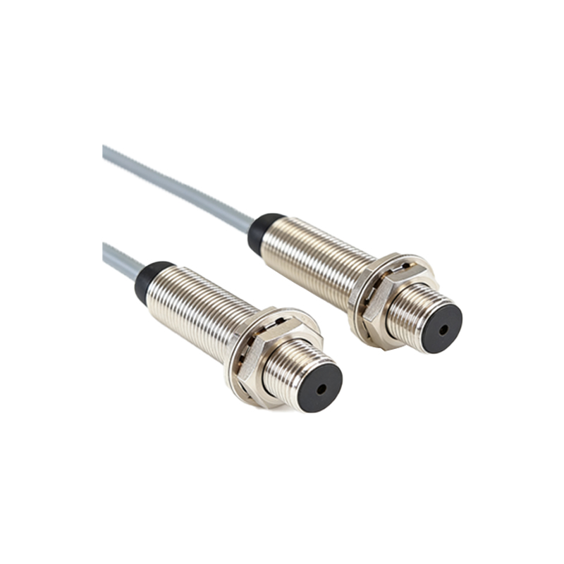
Connect the brown wire to the positive terminal of the DC power supply (+V) and the blue wire to the negative terminal (0V or ground). Use a regulated power source to avoid voltage fluctuations. For long cable runs, consider adding a ferrite bead or filter to reduce electrical noise. Ensure the power supply current rating exceeds the sensor’s consumption, typically under 30mA.
4. Output Wiring and Load Integration
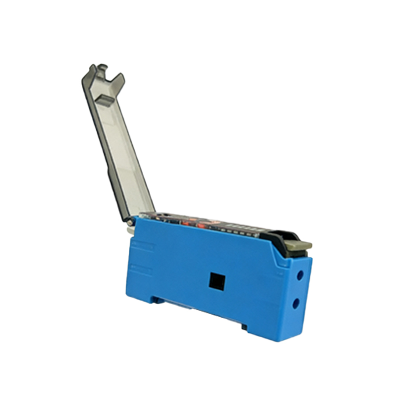
The black wire (normally open) connects to the input of a Programmable Logic Controller (PLC) or relay. For NPN sensors, the output pulls to ground when activated; connect a pull-up resistor if needed. For PNP sensors, the output switches to +V; use a pull-down resistor for stable logic. The white wire (normally closed) works oppositely. Always verify the load current capacity—most sensors drive up to 100mA directly. For higher loads, use an external transistor or relay.
5. Noise Immunity and Grounding
To prevent false triggering, twist the signal and ground wires together. Separate sensor cables from high-voltage or motor cables by at least 15 cm. Use shielded cables in harsh environments, connecting the shield to ground at one end only. Proper grounding of the sensor housing (if metal) reduces electrostatic interference. Test the system under actual operating conditions to ensure stability.
6. Troubleshooting Common Wiring Issues
If the sensor fails to detect objects, first check the power supply voltage at the sensor terminals. Measure output logic with a multimeter—NPN output should read near 0V when active, PNP near +V. Look for loose connections or broken wires. If the output toggles erratically, inspect for stray light entering the slot or cable damage. Replace damaged cables with twisted-pair or shielded types for improved performance.
7. Safety and Best Practices
Always disconnect power before wiring or maintenance. Use fuses on the power line to protect against short circuits. Label wires clearly for future troubleshooting. Follow local electrical codes and the manufacturer’s installation manual. For high-vibration environments, secure cables with clamps and use strain relief. Document the wiring diagram for reference.