Introduction to Phase Detection in Photoelectric Sensors
In industrial automation, phase detection is critical for synchronizing machinery, controlling motor speeds, and ensuring precise timing in processes. Photoelectric sensors, commonly used for object detection, can also be leveraged to determine phase by analyzing the timing of light signals. This article explores the principles, configurations, and practical applications of using photoelectric sensors for phase measurement, tailored for electrical engineers working in manufacturing, robotics, and control systems.
Fundamental Principles of Phase Measurement
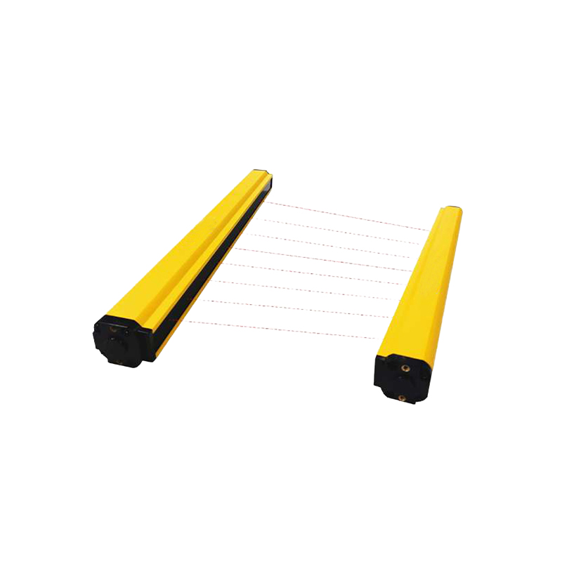
Phase refers to the position of a point in time on a waveform cycle. In photoelectric systems, phase is determined by comparing the timing of received light pulses against a reference signal. Sensors emit light (often infrared or visible) and detect reflections or interruptions. By measuring the delay or shift between emitted and received signals, engineers can calculate phase differences. Key parameters include frequency, duty cycle, and signal edge detection. For example, in through-beam sensors, the interruption of a light beam creates a square wave output; comparing its rising edge to a clock signal reveals phase offset.
Sensor Types and Their Phase Detection Capabilities
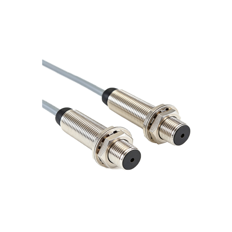
Different photoelectric sensor configurations offer unique phase detection advantages. Through-beam sensors provide high accuracy due to their strong signal-to-noise ratio, making them ideal for phase measurement in high-speed applications. Retro-reflective sensors, while less precise, are cost-effective for moderate-speed systems. Diffuse sensors are suitable for short-range phase detection but may suffer from signal variations due to surface reflectivity. For optimal phase resolution, engineers should select sensors with fast response times (e.g.,< 1 ms) and high repeatability, such as those using modulated light to filter ambient noise.
Signal Processing for Phase Calculation
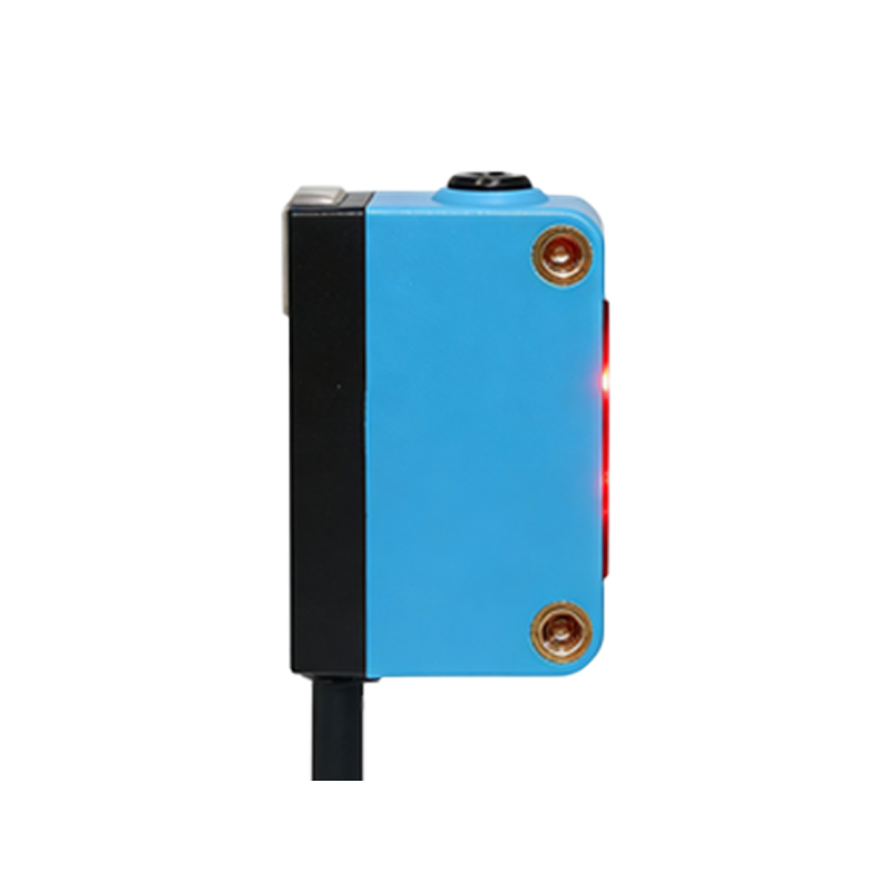
Raw sensor outputs require conditioning for accurate phase determination. Analog signals from photodiodes are amplified and converted to digital pulses via comparators. Microcontrollers or FPGAs then process these pulses using timers or counters. For instance, a phase-locked loop (PLL) can lock the sensor signal to a reference frequency, extracting phase error. Alternatively, time-to-digital converters (TDCs) measure the interval between reference and sensor edges with nanosecond precision. Engineers must consider jitter and noise, implementing filters like moving averages or Kalman filters to stabilize phase readings.
Practical Setup for Phase Detection
To implement phase detection, configure a photoelectric sensor aligned with a rotating encoder or moving target. For example, in conveyor belt synchronization, place a through-beam sensor to detect slots on a wheel. Connect the sensor output to a PLC or dedicated controller. Use a high-speed counter module to capture rising edges and compare them with a master clock. Ensure the sensor’s beam is perpendicular to the target for consistent edge detection. Calibrate the system by measuring phase at known positions, then adjust thresholds in software to compensate for drift.
Applications in Industrial Systems
Phase detection via photoelectric sensors is vital in multi-axis servo systems, where it ensures motors move in unison. In printing presses, it synchronizes roller speeds to prevent misalignment. Robotics use phase data for precise joint positioning. Another example is in packaging machines, where sensors detect product placement phase to trigger cutting mechanisms. For high-frequency applications, such as spindle speed control, sensors with optical fiber interfaces minimize latency. Engineers should note that environmental factors like dust or vibration can degrade phase accuracy, requiring regular maintenance and robust mounting.
Challenges and Solutions in Phase Detection
Common challenges include signal reflection interference, ambient light noise, and target speed variations. To mitigate these, use modulated sensors with specific carrier frequencies (e.g., 10 kHz) to reject background light. Install shields or hoods to reduce stray reflections. For high-speed targets, select sensors with fast rise times (e.g., 10 μs) and use differential signal transmission via RS-422 to preserve timing integrity. Additionally, implement hysteresis in comparators to avoid false triggering due to noise. Regular recalibration against a reference phase source ensures long-term reliability.
Conclusion and Future Trends
Photoelectric sensors offer a robust, cost-effective method for phase detection in many industrial settings. By understanding signal processing, sensor selection, and setup, engineers can achieve phase accuracy within microseconds. Emerging trends include smart sensors with built-in DSP for real-time phase analysis and IoT connectivity for remote monitoring. As automation demands higher precision, integrating photoelectric sensors with machine learning for adaptive phase tuning will become increasingly common. For now, mastering these fundamentals enables reliable phase-based control in your systems.