Understanding the Role of Adjustment Knobs in Background Suppression Sensors
In industrial automation, background suppression photoelectric sensors are critical for reliable object detection, especially in environments with varying backgrounds. The adjustment knob on these sensors allows engineers to fine-tune the detection distance and sensitivity. Unlike standard photoelectric sensors, which may struggle with reflective or multi-colored surfaces, background suppression models use a triangulation principle to ignore objects beyond a set threshold. The knob directly controls this threshold, making precision calibration essential for consistent performance.
Types of Knobs and Their Mechanical Design
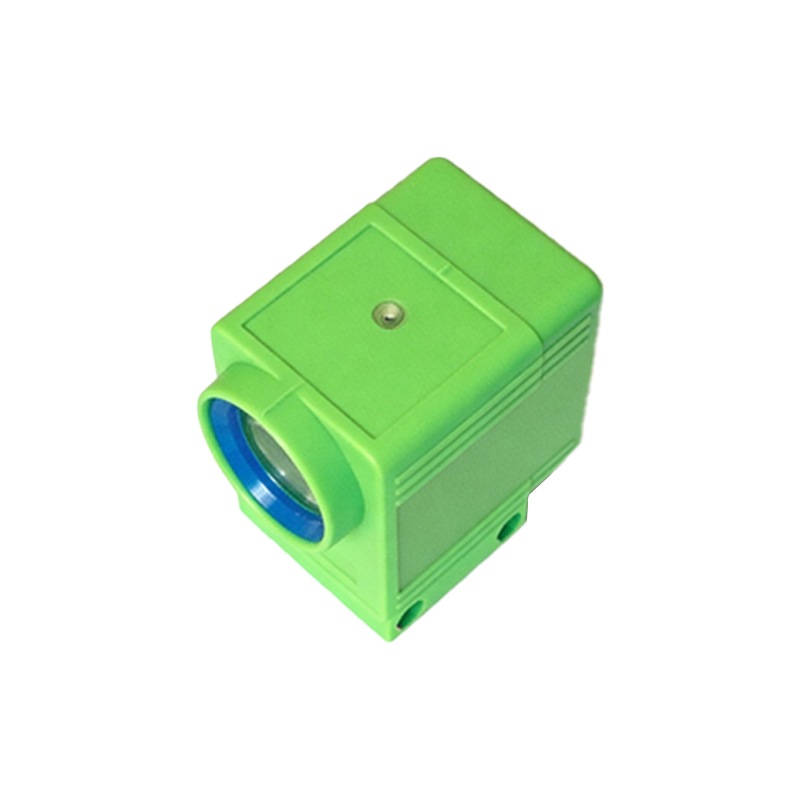
Typical adjustment knobs on background suppression sensors are either potentiometer-based or digital encoder-based. Potentiometer knobs offer a continuous analog adjustment, often marked with a color-coded scale or laser-engraved indicators for quick reference. Digital knobs, found in more advanced models, provide discrete steps with tactile feedback, reducing the risk of unintended drift. Both designs prioritize durability against vibration and dust ingress, featuring sealed O-rings or IP67-rated housings. The knob’s shaft is usually made of brass or stainless steel to resist corrosion in harsh industrial settings.
Calibration Techniques for Optimal Background Suppression
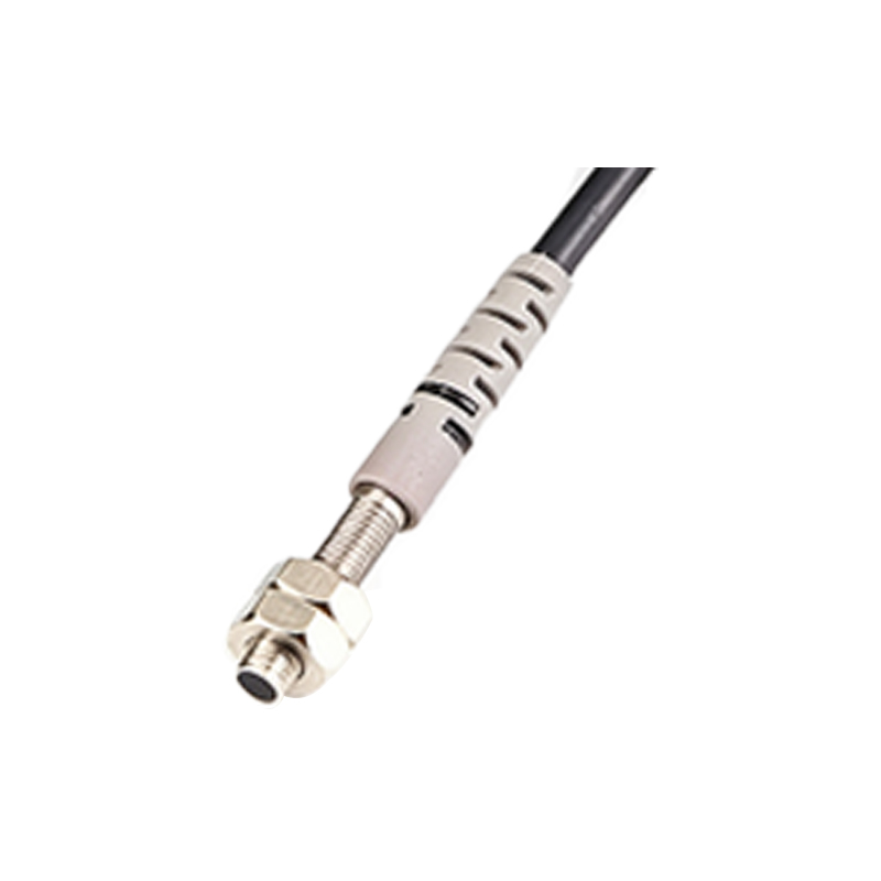
To calibrate a background suppression sensor, first mount the sensor at the desired detection plane. Turn the adjustment knob slowly while observing the LED indicator on the sensor body. Many sensors use a dual-LED system: a steady green light indicates a stable target detection, while a red flash signals background interference. The goal is to set the knob so that the sensor reliably detects the foreground object but ignores any reflective or moving background elements. For dark or glossy surfaces, a slight counterclockwise rotation may reduce false triggers. Always verify calibration with a test run over the full conveyor speed range.
Common Issues and Troubleshooting with Knob Settings
A poorly adjusted knob can lead to intermittent detection or false alarms. If the sensor fails to detect a low-reflectivity target, try incrementally moving the knob clockwise to increase sensitivity. Conversely, if background objects trigger the sensor, reduce the detection range by turning the knob counterclockwise. Environmental factors like dust buildup on the lens or temperature fluctuations may require recalibration. For sensors with multiple knobs, such as separate fine-tune and coarse-tune controls, always adjust the coarse knob first to set the approximate range, then fine-tune for precision.
Maintenance Best Practices for Long-Term Reliability
Regular inspection of the adjustment knob is vital. Over time, mechanical wear or contamination can cause the knob to become stiff or loose. Use a non-abrasive contact cleaner on the potentiometer shaft if resistance is felt. For digital knobs, ensure the detent mechanism is not clogged with debris. Document the optimal knob position for each sensor in your system, either by marking the housing with a permanent marker or logging the value in a PLC. This practice simplifies replacements and reduces downtime during maintenance shifts.