Introduction to Photoelectric Sensors
Photoelectric sensors are essential components in modern industrial automation, converting light signals into electrical outputs for object detection, distance measurement, and position control. As an electrical engineer, understanding their operating principles, types, and application nuances is critical for designing reliable systems. These sensors offer non-contact detection, making them ideal for environments where mechanical switches fail due to wear, contamination, or high-speed operations. This guide covers fundamental concepts, selection criteria, and troubleshooting tips to enhance your practical skills.
Operating Principles and Key Components
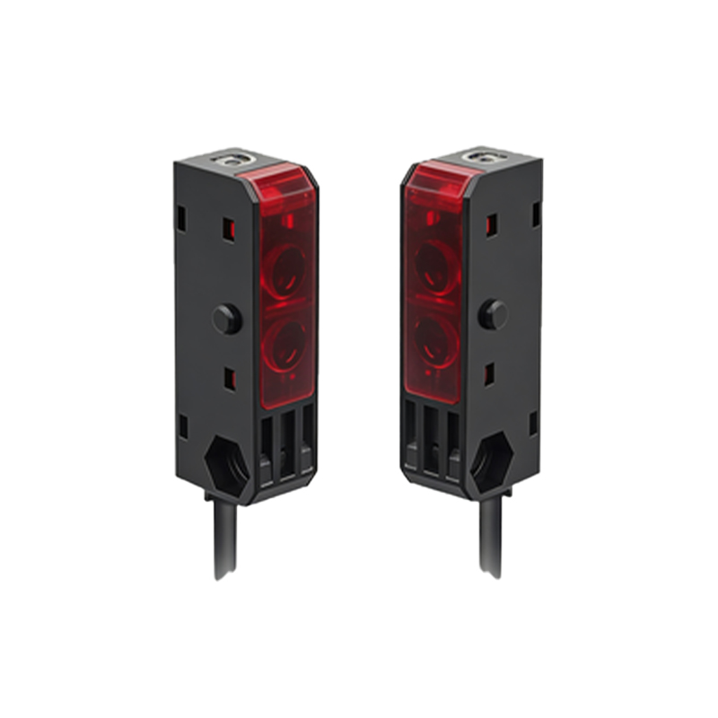
Photoelectric sensors work on the basis of emitting a light beam (typically infrared, visible red, or laser) and detecting changes in the received light intensity. The core elements include an emitter (LED or laser diode), a receiver (photodiode or phototransistor), and a signal processing circuit. The emitter sends a modulated light pulse to avoid interference from ambient light. When an object interrupts or reflects the beam, the receiver triggers an output signal. Key parameters to consider are sensing range, response time, and ambient light immunity. For instance, laser sensors provide longer ranges (up to 100 meters) but require precise alignment, while LED sensors are more cost-effective for short to medium distances.
Types of Photoelectric Sensors and Their Applications
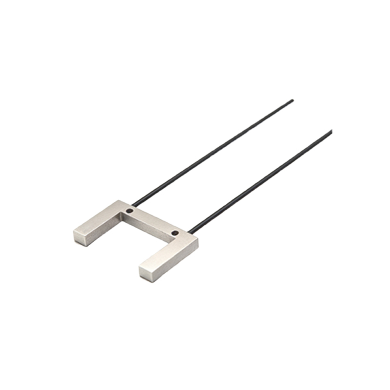
There are three primary configurations: through-beam, retro-reflective, and diffuse reflective. Through-beam sensors have separate emitter and receiver units, offering the longest range and highest reliability but requiring wiring at both ends. They are ideal for conveyor belt monitoring and security barriers. Retro-reflective sensors use a reflector to bounce the beam back, simplifying installation while maintaining good range. Diffuse reflective sensors combine emitter and receiver in one housing, detecting objects by reflected light; they are suitable for opaque materials but less effective on shiny or transparent surfaces. For example, in packaging lines, diffuse sensors detect cardboard boxes, while retro-reflective units handle clear plastic bottles with a polarizing filter.
Selection Criteria for Industrial Environments
Choosing the right sensor involves evaluating environmental factors: dust, moisture, temperature, and background interference. For dusty environments, through-beam sensors are preferable as they are less prone to false triggers. In wet conditions, use sensors with IP67 or higher ratings. Background suppression technology is crucial for applications with variable backgrounds, such as detecting objects on a conveyor belt with changing colors. Response time must match the production speed; a sensor with a 1 ms response time can detect objects moving at 10 m/s with a 10 mm margin. Power supply voltage (e.g., 10-30 VDC) and output type (NPN or PNP) must align with the control system, typically PLC inputs.
Installation and Alignment Best Practices
Proper installation ensures optimal performance. For through-beam sensors, align the emitter and receiver precisely using a laser sight or alignment tool. Ensure the beam path is clear of obstructions and reflective surfaces. For retro-reflective sensors, mount the reflector perpendicular to the beam axis and avoid shiny surfaces nearby that could cause stray reflections. Diffuse sensors require a dark background or a background suppression sensor to prevent false detection. Use shielded cables in high-EMI areas and avoid parallel routing with power lines. After installation, perform a functional test with the actual target material at the minimum and maximum distances.
Troubleshooting Common Issues
Common problems include false triggering, no detection, or intermittent operation. False triggering often arises from ambient light interference, such as sunlight or welding arcs; use sensors with modulated light and optical filters, or install shades. No detection may result from misalignment, dirty lenses, or an unsuitable sensing mode for the target material (e.g., transparent objects). Intermittent operation is frequently caused by loose connections, voltage drops, or temperature drift. For example, if a sensor fails near a metal surface, switch to a model with background suppression or adjust the sensitivity. Regular cleaning of lenses with a lint-free cloth and alcohol helps maintain accuracy.
Calibration and Maintenance Tips
Calibration typically involves adjusting the sensitivity potentiometer or using a teach-in button. Start with the lowest sensitivity and increase until the sensor reliably detects the target without false triggers. For teach-in sensors, place the target at the desired position and follow the manufacturer’s procedure. Document calibration settings for reproducibility. Maintenance schedules should include checking for lens contamination, cable integrity, and alignment every 3-6 months in harsh environments. Use a test piece identical to the actual product to verify performance. Replacing sensors proactively before failure in critical applications reduces downtime.
Advanced Topics: Fiber Optic and Laser Sensors
Fiber optic sensors extend the capabilities of photoelectric sensors in confined spaces or high-temperature areas, using flexible fiber cables to separate the electronics from the sensing head. Laser sensors offer precision for micrometer-level measurements, such as in semiconductor manufacturing. Both types require careful handling and calibration. For fiber optics, ensure the cable bend radius exceeds the minimum specified to avoid light loss. Laser sensors must comply with safety regulations (e.g., Class 1 or 2 lasers) and require protective eyewear during alignment. Integration with industrial Ethernet, such as IO-Link, allows real-time diagnostics and parameter adjustments.
Conclusion: Enhancing System Reliability
Mastering photoelectric sensors requires a blend of theoretical knowledge and hands-on experience. By selecting the appropriate type, installing correctly, and performing regular maintenance, you can significantly improve system reliability and efficiency. Stay updated with industry standards (e.g., IEC 60947-5-2) and new technologies like smart sensors with self-diagnostics. Apply these principles in your next project to achieve robust automation solutions.