Introduction to Photoelectric Sensor Conversion Modules
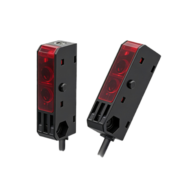
Photoelectric sensor conversion modules are critical components in modern industrial automation systems. These modules bridge the gap between raw optical signals generated by photoelectric sensors and the digital or analog inputs required by programmable logic controllers (PLCs) or distributed control systems (DCS). As an electrical engineer specializing in sensor integration, I often encounter challenges related to signal noise, distance limitations, and compatibility with legacy systems. The conversion module addresses these issues by conditioning, amplifying, and translating the sensor's output into a standardized format, such as 4-20 mA current loops, 0-10 VDC voltage signals, or discrete NPN/PNP transistor outputs. This ensures reliable data transmission over long distances and in harsh industrial environments.
Core Components and Signal Flow
At the heart of the conversion module lies a photodiode or phototransistor that detects light emitted by the sensor's LED. The incident light intensity varies based on the target object's presence, reflectivity, or color. This optical signal is converted into a low-level electrical current, typically in the microampere range. A transimpedance amplifier (TIA) then converts this current into a voltage signal while providing high gain and low noise. The voltage signal passes through a comparator stage, where a reference threshold is set via a potentiometer or digital-to-analog converter (DAC). The comparator output triggers a switching transistor or an operational amplifier configured for linear output. For analog modules, a voltage-to-current converter (V/I converter) generates the standard 4-20 mA signal, ensuring immunity to voltage drops in long cable runs.
Key Electrical Parameters and Design Considerations
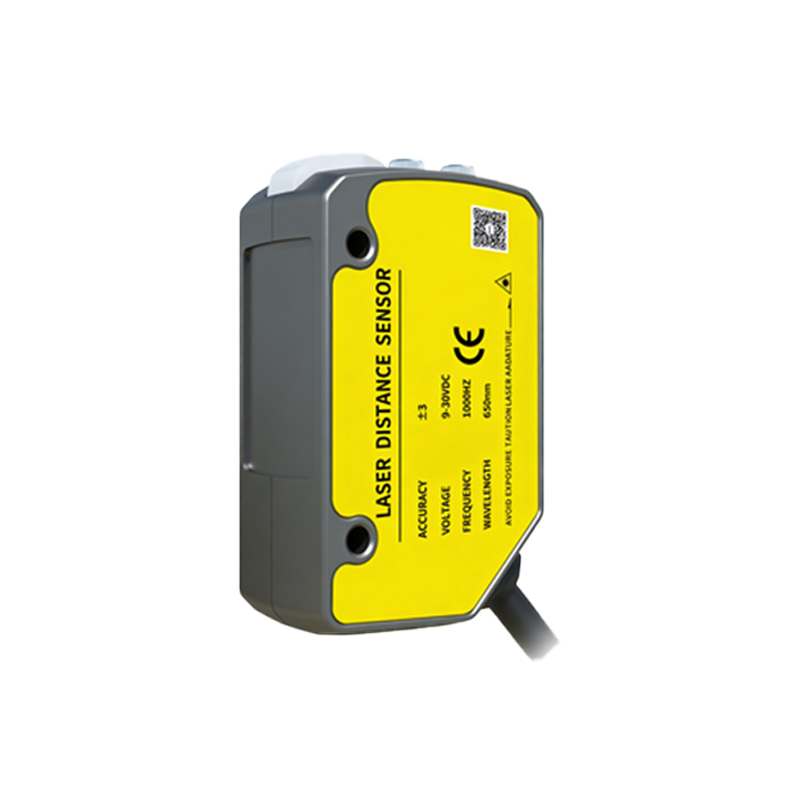
When selecting or designing a conversion module, engineers must evaluate several key parameters. The response time, often specified in microseconds, determines the module's ability to detect fast-moving objects on a conveyor line. The hysteresis level prevents oscillation near the detection threshold, a common issue in noisy environments. The supply voltage range, typically 10-30 VDC, must accommodate industrial power sources. Additionally, the output protection features, such as short-circuit protection and reverse polarity protection, are essential to prevent damage during installation or maintenance. I recommend using modules with galvanic isolation between the input and output stages to eliminate ground loop interference, which can cause false triggers in multi-sensor setups.
Signal Conditioning and Noise Mitigation Techniques
In practice, industrial environments introduce electromagnetic interference (EMI) from motors, variable frequency drives (VFDs), and welding equipment. The conversion module's Printed Circuit Board (PCB) layout incorporates ground planes, shielded traces, and decoupling capacitors to filter high-frequency noise. For low-level optical signals, a synchronous demodulation technique can be applied. The LED is pulsed at a known frequency, and the conversion module's receiver uses a bandpass filter tuned to that frequency. This rejects ambient light from fluorescent lamps or sunlight, which is a common failure point in standard photoelectric sensors. Furthermore, a Schmitt trigger circuit with adjustable hysteresis ensures clean digital transitions even with slowly changing light levels.
Calibration and Application Considerations
Field calibration is straightforward for most modules. The sensitivity potentiometer adjusts the reference voltage at the comparator, allowing the engineer to set the detection distance or contrast level. For example, in a bottle-filling line, the module must differentiate between a clear glass bottle and a dark background. The output configuration selector allows switching between light-on (NO) and dark-on (NC) modes. When integrating with a PLC, pay close attention to the sinking versus sourcing output type. A PNP (source) output is commonly used in European systems, while NPN (sink) outputs are prevalent in Asian markets. The module should also include an LED indicator for local diagnostics, showing the output state and power status.
Advanced Features and Future Trends
Recent advancements include IO-Link communication capabilities, which provide bidirectional data exchange between the sensor module and the controller. This enables remote configuration, predictive maintenance alerts, and real-time quality monitoring. Some modules now incorporate an integrated microcontroller for self-diagnostics, such as detecting lens contamination or LED degradation. As Industry 4.0 evolves, conversion modules are becoming more compact, with surface-mount technology (SMT) reducing size while increasing reliability. Engineers should also consider modules with adjustable response times to optimize for both speed and stability. For hazardous locations, intrinsically safe versions with zener barriers ensure compliance with ATEX or IECEx standards.