Understanding the E3FA4 Photoelectric Sensor
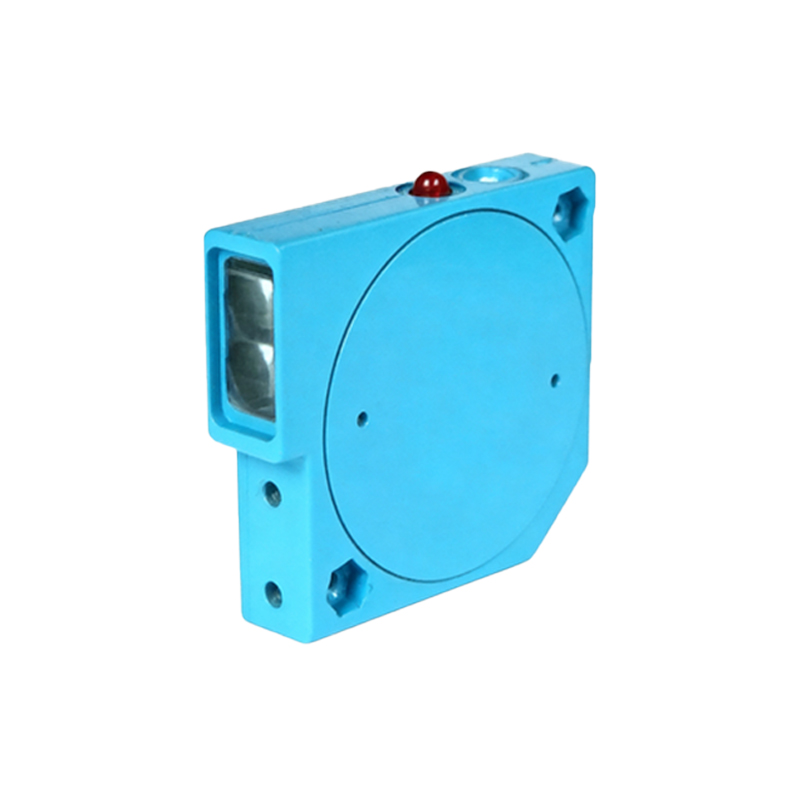
The Omron E3FA4 is a widely used photoelectric sensor in industrial automation, designed for reliable object detection in harsh environments. It features a through-beam or retro-reflective mode, depending on the model, and requires a 4-wire connection for proper operation. This sensor operates on a 12-24 VDC power supply and provides both NPN and PNP output options, making it compatible with most PLCs and control systems. Proper wiring is critical to ensure signal integrity and prevent electrical noise interference.
Identifying the 4 Wires of the E3FA4
The E3FA4 sensor typically has four color-coded wires: brown, blue, black, and white. The brown wire is the positive power supply line (+V), the blue wire is the negative power supply line (0V or GND), the black wire is the output signal (typically NPN or PNP), and the white wire is the test input or alarm output, depending on the configuration. Before wiring, always consult the sensor’s datasheet to confirm the exact function of the white wire for your specific model. Using a multimeter in continuity mode can help verify wire assignments if labels are unclear.
Wiring the Power Supply for the E3FA4
Connect the brown wire to the positive terminal of a 12-24 VDC power supply, and the blue wire to the negative terminal or ground. Ensure the power supply is stable and within the specified voltage range to avoid damaging the sensor’s internal electronics. Use a fused power source to protect against short circuits. For long cable runs, consider using shielded cables to minimize electromagnetic interference, especially in industrial environments with heavy machinery.
Connecting the Output Signal to a PLC or Controller
The black wire carries the output signal. For an NPN output (sinking), connect the black wire to the input terminal of the PLC, and ensure the load is connected between the output and the positive power supply. For a PNP output (sourcing), connect the black wire to the input terminal, with the load connected between the output and ground. Verify the PLC input type (sinking or sourcing) to match the sensor’s output configuration. If using a relay, wire the black wire to the coil terminal with a freewheeling diode for inductive load protection.
Using the Test or Alarm Wire (White Wire)
The white wire can serve as a test input or alarm output. In standard operation, leave this wire unconnected or ground it to enable normal sensing. If the sensor includes a test function, applying a brief 0V signal to the white wire will temporarily disable the output for diagnostic purposes. Alternatively, some models use the white wire to output an alarm signal when the sensor detects a fault, such as a dirty lens or alignment issue. Always refer to the product manual to confirm the behavior for your specific E3FA4 variant.
Testing and Troubleshooting the Wiring
After completing the connections, power on the system and test the sensor by placing an object in its detection range. Use a multimeter to measure the voltage at the black wire: it should switch between 0V and the supply voltage based on the sensor’s state. If the output remains constant, check the wiring polarity and ensure the white wire is properly grounded. Inspect the sensor’s indicator LED: a steady green light typically indicates normal operation, while a flashing red light may signal an alignment or wiring error. Recheck all connections for loose terminals or damaged insulation.