Introduction to Planar Positioning Photoelectric Sensors
Planar positioning photoelectric sensors are crucial components in modern industrial automation, enabling precise detection and alignment of objects within a two-dimensional plane. Unlike traditional point-based sensors, these devices utilize advanced optical principles to determine the exact location, orientation, or displacement of a target along X and Y axes. They are widely deployed in applications such as PCB assembly, robotic arm guidance, and conveyor belt sorting, where micron-level accuracy is required. By emitting modulated light beams and analyzing reflections or interruptions, they offer non-contact measurement, reducing wear and maintenance. This article delves into their working principles, technical specifications, and practical deployment strategies.
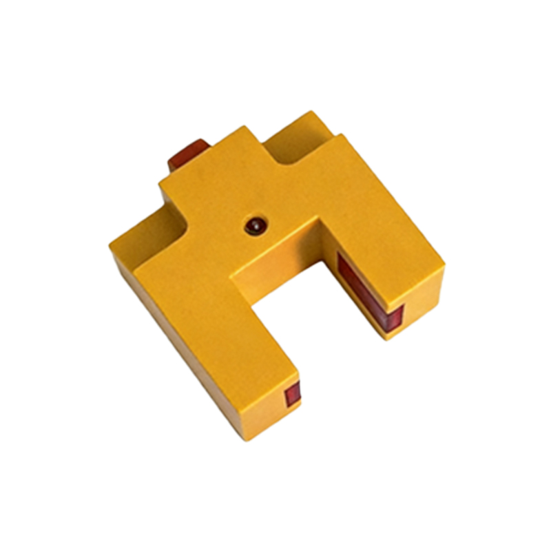
Working Principle and Core Technologies
The fundamental operation relies on triangulation or time-of-flight methods. In a typical setup, a light source (e.g., laser diode or LED) projects a structured pattern, such as a line or grid, onto the target surface. A high-resolution photodetector array captures the reflected pattern. Any positional change alters the incident angle or pattern distortion, which is processed by an onboard microcontroller to calculate displacement. Advanced models incorporate background suppression to ignore irrelevant surfaces and ambient light filtering for stability in harsh environments. Key parameters include resolution (down to 1 micron), response time (under 1 ms), and measuring range (from 10 mm to 2 m). These sensors often support communication protocols like IO-Link or EtherCAT for seamless integration into PLC systems.
Key Technical Specifications to Consider
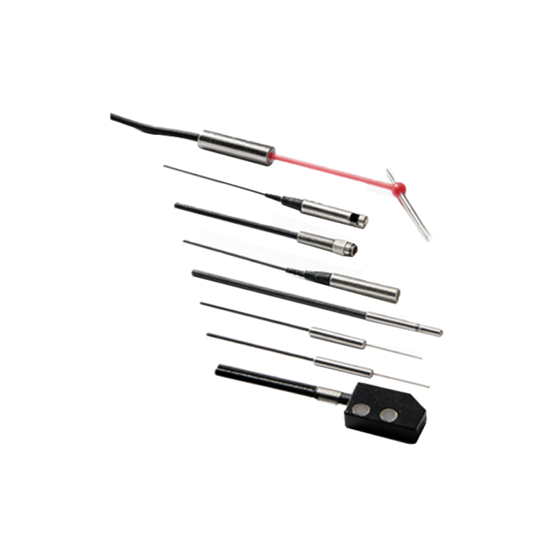
When selecting a planar positioning photoelectric sensor, engineers must evaluate several critical specs. First, linearity error: ensure it is below ±0.1% of full scale for consistent accuracy. Second, repeatability: look for values within ±2 microns to guarantee reliable cycles. Third, environmental robustness: IP67 or higher rating is essential for dusty or wet factory floors. Additionally, temperature drift compensation is vital, as thermal expansion can skew readings. Output types—analog (0-10 V or 4-20 mA) or digital (RS-485 or Ethernet)—should match the control system architecture. For dynamic applications, consider the sampling rate: at least 10 kHz for fast-moving targets. Finally, check the sensor’s beam divergence angle to avoid cross-talk in dense installations.
Installation and Configuration Best Practices
Proper installation maximizes sensor performance. Begin by mounting the sensor perpendicular to the target plane to minimize angular errors. Use rigid brackets to absorb mechanical vibrations. Align the light beam so it covers the entire target area without obstruction. For calibration, perform a zero-point adjustment with a reference block positioned at the sensor’s nominal distance. Configure the output via software tools to set thresholds, hysteresis, and filter coefficients. In multi-sensor arrays, stagger their mounting heights to prevent interference. Regularly clean the lens with lint-free cloths and isopropyl alcohol to maintain optical clarity. Document all setup parameters for troubleshooting.
Common Applications in Industrial Automation
These sensors excel in tasks demanding spatial accuracy. In semiconductor manufacturing, they align wafers before lithography, ensuring overlay precision. For automated guided vehicles (AGVs), they detect pallet slots for loading/unloading. In packaging lines, they verify label placement on cartons with tolerance below 0.5 mm. Another niche is in 3D printer bed leveling, where they measure axis tilt. The automotive sector uses them for checking sealant bead paths on car bodies. Their ability to operate in high-speed cycles (over 1000 parts per minute) makes them ideal for pick-and-place robots. Case studies show a 40% reduction in scrap rates after upgrading from mechanical limit switches.
Troubleshooting and Maintenance Tips
Common issues include false triggers due to reflective backgrounds or stray light. Mitigate by enabling background suppression or using polarizing filters. If readings drift, check for lens contamination or thermal instability—allow the sensor to warm up for 15 minutes. Electrical noise from nearby motors can corrupt signals; use shielded cables and ferrite beads. When the sensor fails to detect, verify the target’s reflectivity (matte surfaces may need higher gain). For software glitches, reset the device to factory defaults and re-upload configuration. Schedule quarterly inspections: clean optics, tighten connections, and run diagnostic tests via the manufacturer’s software. Keep spare units for rapid replacement.
Future Trends and Innovations
The evolution of planar positioning sensors is driven by Industry 4.0 demands. Emerging technologies include hybrid sensors combining photoelectric and ultrasonic methods for multi-material detection. AI-powered algorithms now predict sensor drift and auto-calibrate. Miniaturization has produced sensors smaller than a coin, enabling integration into compact grippers. Wireless options using Bluetooth 5.0 allow remote monitoring. Additionally, time-resolved imaging sensors achieve sub-nanosecond timing for ultra-fast sorting. As factories adopt digital twins, sensor data will feed into simulation models for predictive maintenance. The next frontier is quantum dot-based photodetectors offering near-zero noise, pushing resolution to atomic scales.