Understanding the ST181 Photoelectric Sensor
The ST181 is a widely used photoelectric sensor in industrial automation, known for its reliable through-beam and retro-reflective detection capabilities. It operates on a DC power supply, typically 10-30V, and features a PNP or NPN output configuration. Proper wiring is critical to ensure stable operation in harsh environments, such as dusty factories or moisture-prone areas. Before starting, always verify the sensor model and its datasheet to confirm voltage and output type. The sensor includes three primary wires: brown (power positive), blue (power negative), and black (output signal). For retro-reflective models, there may be an additional white wire for synchronization.
Wiring Diagram and Color Code
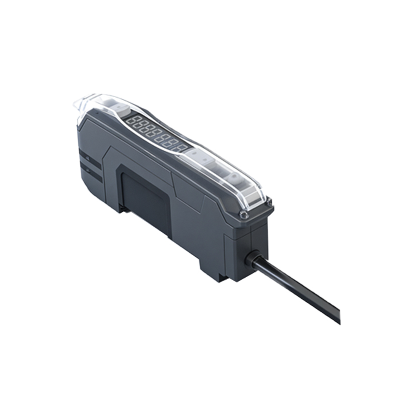
Begin by connecting the brown wire to the positive terminal of a DC power supply (e.g., +24V). Connect the blue wire to the negative terminal (0V). For PNP output sensors, the black wire connects to the load (e.g., a PLC input), and the load is tied to ground. For NPN output sensors, the black wire connects to the load, and the load is tied to the positive supply. The white wire, if present, is used for synchronizing multiple sensors. Use a multimeter to verify continuity before powering on. Ensure the cable shield (if present) is grounded at one end to reduce electromagnetic interference. Common wiring errors include reversed polarity, which can damage the sensor, or loose connections causing intermittent faults.
Testing and Troubleshooting the Connection
After wiring, power up the system and check the indicator LED on the sensor. A steady green light typically indicates normal operation, while red or blinking lights may signal alignment issues or wiring faults. Test the sensor by placing an object in its detection path. For through-beam sensors, ensure the emitter and receiver are aligned. For retro-reflective models, check the reflector alignment. Use a PLC or oscilloscope to monitor the output signal. Common issues include voltage drop due to long cable runs, which can be mitigated by using thicker gauges. Also, verify that the load impedance matches the sensor output. If the sensor fails to respond, double-check the connection to the load and ensure the power supply is stable.
Safety and Installation Best Practices
Always disconnect power before wiring to avoid electric shock or short circuits. Use shielded cables for noisy environments and maintain a minimum bending radius to prevent wire breakage. Install the sensor at the correct distance from the target to optimize sensitivity. For outdoor or washdown applications, use IP67-rated enclosures and seal all connectors with silicone. Label all wires clearly for future maintenance. If using multiple ST181 sensors, ensure they do not interfere optically by spacing them properly. Finally, document the wiring diagram in your system manual for troubleshooting reference.