In modern industrial automation and electronic systems, proximity sensors serve as critical components for non-contact detection, object positioning, and process control. A proper proximity sensor connection is fundamental to ensuring reliable operation, accuracy, and system safety. This guide details the essential principles, wiring methods, and best practices for connecting various types of proximity sensors.
Understanding the core types is the first step. Inductive proximity sensors detect metallic objects and typically have three or four wires. Capacitive sensors can detect both metallic and non-metallic materials and share similar wiring schemes. The two primary output configurations are PNP (sourcing) and NPN (sinking), which dictate how the sensor interfaces with the controller's input module, such as a PLC.
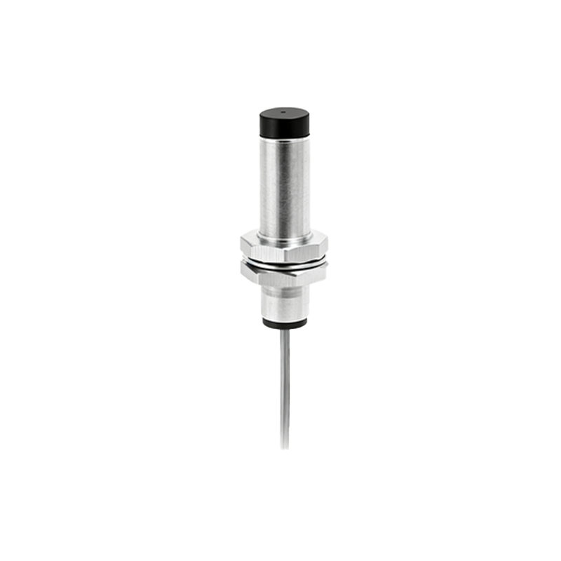
A standard 3-wire DC sensor has brown (V+), blue (V- or common), and black (output signal) wires. For a PNP sensor, the brown wire connects to the positive DC supply (e.g., +24VDC), the blue wire to the negative or 0V, and the black wire carries the switched positive signal to the PLC input. The PLC input completes the circuit by connecting internally to common (0V). Conversely, for an NPN sensor, wiring remains identical for power (brown to +V, blue to 0V), but the black output wire switches the negative side. Here, the black wire connects to the PLC input, and the PLC input's internal circuit connects to positive, completing the path to 0V when the sensor activates.
Four-wire sensors often incorporate two output channels—one normally open (NO) and one normally closed (NC)—or sometimes a complementary PNP and NPN output pair. Always consult the manufacturer's datasheet for the exact pinout and wiring diagram. Shielded cables are highly recommended for long cable runs or electrically noisy environments. The cable shield should be grounded at only one end, typically at the control panel, to prevent ground loops.
Key connection practices include ensuring a stable, clean power supply within the sensor's rated voltage range. Voltage spikes or ripple can cause erratic behavior. Fusing the power supply line close to the source protects against short circuits. For sensors in AC configurations, typically two-wire types, ensure correct load current compatibility to avoid malfunction. Maintain proper polarity for DC sensors; reversing power can permanently damage the internal electronics.
Environmental considerations are crucial. Use connectors with adequate IP ratings for the application's dust and moisture conditions. Secure all connections mechanically to prevent vibration-induced failures. During installation, keep sensor cables away from high-voltage power lines and motor drives to minimize electromagnetic interference. A final functional test with the target object at the specified sensing distance verifies correct installation and alignment.
Troubleshooting often starts at the connection point. A sensor that fails to trigger may have incorrect wiring, a faulty power supply, or an overloaded output. Use a multimeter to check for supply voltage at the sensor terminals and observe the output state change when a target is present. Indicator LEDs on the sensor are invaluable for diagnosing power and output status. Remember, a consistently reliable proximity sensor connection forms the backbone of efficient and fail-safe automated systems, reducing downtime and maintenance costs.