The crankshaft position sensor is a critical component in modern internal combustion engines. While technical descriptions are valuable, sometimes a picture is worth a thousand words. This visual guide uses detailed images and diagrams to explain the sensor's function, common failure signs, and the replacement process, providing a clear understanding for both enthusiasts and technicians.
Understanding the Sensor Through Diagrams
A cross-sectional diagram of an engine block is the best starting point. This image typically shows the sensor mounted on the engine, often near the bell housing (where the engine meets the transmission) or on the front of the engine near the crankshaft pulley. The diagram highlights its proximity to the reluctor ring—a notched wheel attached to the crankshaft or flywheel. Close-up illustrations reveal the sensor's tip, which houses a magnetic coil or a Hall-effect chip. A clear visual shows how the gaps in the rotating reluctor ring alter the magnetic field or interrupt a signal, generating a precise voltage pulse for each cylinder. This pulse train is the essential "timing signal" sent to the Engine Control Unit (ECU).
Visual Catalog of Sensor Types and Locations
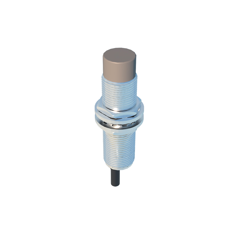
Real-world photos are indispensable for identification. Images of common sensor types show distinct differences: the two-pin or three-pin electrical connector, the often black plastic or metallic body, and the mounting bolt hole. A series of photos can demonstrate common locations: for a front-mounted sensor, a picture might show it pointing towards the crankshaft pulley's harmonic balancer. For a rear-mounted sensor, an image could depict it threaded into the side of the bell housing, aimed at the flywheel's teeth. Side-by-side comparisons of sensors from different manufacturers (like Bosch, Delphi, or Denso) reveal subtle variations in shape and connector style, aiding in correct part identification.
Picturing Symptoms of Failure
Certain images strongly correlate with a failing sensor. A dashboard warning light, specifically the "Check Engine" icon illuminated, is the most universal sign. A diagnostic trouble code (DTC) reader display showing codes P0335 (Crankshaft Position Sensor "A" Circuit Malfunction) or P0336 (Circuit Range/Performance) provides direct electronic evidence. More dramatic visuals include a car stranded on the roadside, representing a no-start condition—a common failure mode where the engine cranks but won't fire because the ECU receives no signal. While not a direct image of the sensor, a graph from an oscilloscope display showing an erratic or missing signal waveform compared to a clean, uniform pattern offers a technical visualization of the fault.
Step-by-Step Replacement in Images
A photo guide for replacement demystifies the process. It begins with a safety shot: disconnecting the negative battery terminal. Next, a clear image locates the specific sensor in the engine bay, often requiring the removal of an air intake hose or other components for access. A close-up shows the electrical connector's locking tab being depressed before unplugging it. A crucial image demonstrates the proper tool—usually a socket, wrench, or specialized sensor removal tool—loosening the single mounting bolt. A picture of the old sensor being pulled straight out from its bore is key, warning against angled removal that could cause damage.
The installation sequence is shown in reverse. An important visual detail is applying a small amount of engine oil or specific sensor-safe antiseize to the new sensor's O-ring (if equipped) before insertion. A torque wrench set to the manufacturer's specification (often a low value like 8-10 Nm) tightening the bolt emphasizes proper installation. The final images show the connector securely snapped back into place and the engine components reassembled, concluding with the engine running smoothly and the check engine light off after code clearance.
Internal Inspection and Damage Close-ups
For the curious, macro photographs of a failed sensor can be revealing. Images might show physical damage like a cracked housing or a chipped tip. Corrosion on the electrical pins is a common and clear visual indicator of failure. While less common, pictures might show metallic debris stuck to a magnetic-type sensor's tip, attracted from a failing reluctor ring or bearing. These close-ups solidify the understanding of how environmental factors and mechanical wear lead to sensor demise.
In conclusion, crankshaft position sensor images, from schematic diagrams to real-world repair photos, serve as a powerful educational tool. They bridge the gap between abstract electronic theory and practical automotive repair, enabling accurate diagnosis, correct part selection, and confident DIY maintenance or professional service.