Selecting the appropriate cable for a proximity sensor is a critical yet often overlooked aspect of industrial automation and machinery design. The right cable ensures reliable signal transmission, protects against environmental hazards, and extends the operational lifespan of both the sensor and the connected control system. A poor choice can lead to intermittent failures, inaccurate readings, and costly downtime. This guide outlines the key factors to consider when specifying a cable for inductive, capacitive, or other types of proximity switches.
First, understand the electrical requirements of your sensor. Most standard 3-wire DC proximity sensors require a cable with conductors for power supply (typically brown and blue wires) and a switched output signal (black wire). The cable must match the sensor's voltage rating and current-carrying capacity. For analog output sensors or sensors with IO-Link functionality, additional conductors are necessary. Always consult the sensor's datasheet for the required number of cores, conductor cross-sectional area (e.g., 0.34 mm²), and any shielding specifications. Using an undersized cable can cause voltage drop and signal degradation over long distances.
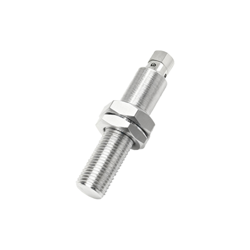
The operating environment dictates the cable's mechanical and material construction. For fixed installations in control cabinets with minimal movement, a standard PVC jacket may suffice. However, for applications involving continuous flexing, such as on cable carriers or robotic arms, you must choose a highly flexible cable designed for high cycle counts. These cables feature finely stranded conductors and special elastomer jackets that resist cracking. In areas with exposure to oils, coolants, or chemicals, select a cable with a polyurethane (PUR) or thermoplastic elastomer (TPE) jacket that offers superior resistance. For washdown environments in food and beverage or pharmaceutical industries, cables must withstand high-pressure cleaning and often require FDA-compliant or antimicrobial jackets.
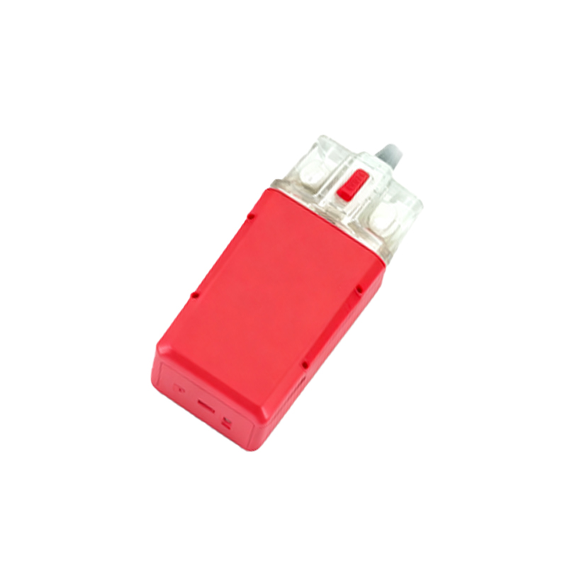
Electromagnetic interference (EMI) is a major concern in plants with variable frequency drives, motors, and welding equipment. Shielded cables are essential to prevent noise from corrupting the sensor's signal. A braided copper shield provides good overall protection, while a foil shield offers 100% coverage against high-frequency interference. Often, a combination of both is used. The shield must be properly grounded at the control system end to be effective. For particularly noisy environments or for analog sensors where signal integrity is paramount, consider double-shielded or individually shielded pair designs.
Don't neglect the connector. Most industrial proximity sensors use a quick-disconnect (QD) style connector, such as M8 or M12 types, with 3, 4, or 5 pins. The cable must be terminated with the matching connector, and the IP (Ingress Protection) rating of the connector-cable assembly should match or exceed the sensor's rating. For sensors with an integral cable (potted cable), ensure the cable entry is properly strain-relieved to prevent wire breakage from vibration or pulling. For harsh environments, choose connectors with metal housings and higher IP ratings (e.g., IP67 or IP69K).
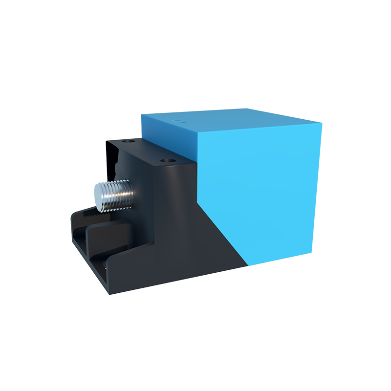
Finally, consider installation practices and standards. Adhere to minimum bending radii during installation to avoid damaging internal conductors. Use cable ties appropriately—over-tightening can compress and damage the jacket and shield. For long cable runs, secure the cable at regular intervals to prevent stress on the connector. Always follow local electrical codes and machinery safety standards (e.g., IEC, NEC). Investing in a higher-quality cable from a reputable manufacturer may have a higher upfront cost but pays dividends in reduced maintenance and improved system reliability. By systematically evaluating the electrical needs, environmental challenges, and installation realities, you can select a proximity sensor cable that guarantees precision, durability, and seamless integration into your automated processes.