Power type proximity sensors are widely used in industrial automation for detecting the presence or absence of objects without physical contact. Proper wiring is crucial for ensuring reliable operation and preventing damage to the sensor or connected equipment. This guide provides a comprehensive overview of wiring methods, considerations, and best practices for power type proximity sensors.
Most power type proximity sensors operate on DC or AC voltage, typically ranging from 10-30V DC or 90-250V AC. The sensor consists of three main terminals: power supply (V+ or L+), ground (V- or L-), and output (NO/NC). Before wiring, always refer to the manufacturer's datasheet for specific voltage ratings, current limits, and terminal designations. Incorrect voltage application can lead to immediate failure or reduced lifespan.
For DC sensors, connect the positive power supply wire to the V+ terminal and the negative wire to the V- terminal. The output terminal is then connected to the load, such as a PLC input module, relay, or indicator light. Ensure the load current does not exceed the sensor's maximum switching capacity. A common mistake is reverse polarity connection, which may permanently damage internal circuits. Some sensors include reverse polarity protection, but it is not universal.
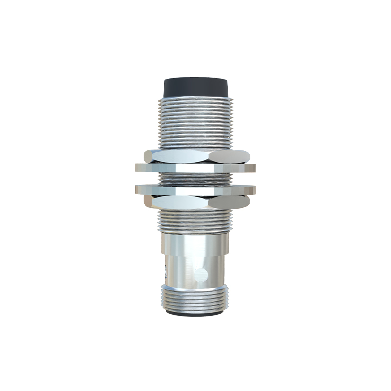
AC-powered sensors follow a similar principle but require attention to phase and neutral wires. Connect the live wire to the L+ terminal and the neutral wire to the L- terminal. The output terminal switches the load accordingly. Since AC sensors often have higher voltage ratings, use insulated tools and ensure power is disconnected during installation. Grounding the sensor housing is recommended to prevent electrical noise interference, especially in environments with motors or frequency inverters.
Shielded cables are advisable for long wiring runs or electrically noisy areas. The shield should be grounded at one end only, typically at the control panel, to avoid ground loops. Keep sensor cables separate from high-voltage power lines by at least 10-15 cm to minimize inductive coupling. For multi-sensor installations, use individual conduits or cable trays to organize wiring and simplify troubleshooting.
Output configurations include normally open (NO) and normally closed (NC). In NO configuration, the output circuit closes when an object is detected, allowing current to flow. In NC configuration, the output circuit opens upon detection. Choose based on the control logic requirements. Some sensors offer programmable outputs or short-circuit protection features, enhancing flexibility and safety.
Testing after wiring is essential. Apply power and verify the sensor's indicator LED behavior. Most sensors have a LED that illuminates when powered and changes state upon detection. Use a test object within the specified sensing range to confirm output switching. If the sensor fails to respond, double-check wiring connections, voltage levels, and load compatibility. Environmental factors like temperature, humidity, or contamination can also affect performance.
Maintenance involves periodic inspection for loose connections, cable damage, or corrosion. Clean the sensor face regularly to prevent false triggers from dust or debris. Record wiring diagrams and sensor locations for future reference, especially in complex systems. Adhering to these practices ensures optimal functionality and extends the operational life of power type proximity sensors in diverse applications.