In the realm of industrial automation, robotics, and precision measurement, laser sensors play a pivotal role. A fundamental concept governing their operation, particularly for diffuse reflection types, is the reflective area formula. This formula is not merely an abstract equation but a practical tool for engineers and technicians to predict and optimize sensor performance in real-world applications.
At its core, a laser sensor operates by emitting a focused beam of light towards a target. The sensor then detects the light reflected back. The amount of light received by the sensor's receiver is directly proportional to the intensity of the reflected beam. This is where the concept of reflective area becomes critical. For a given target surface, the effective area that reflects light back to the sensor's receiver lens determines the signal strength.
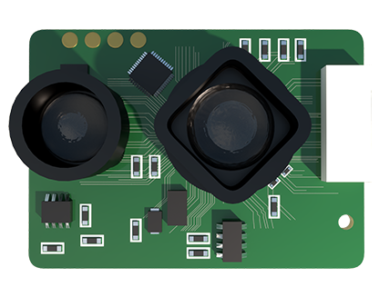
The reflective area formula is derived from principles of geometry and optics. Consider a standard setup: a laser sensor with a defined beam divergence angle is positioned at a specific distance from a target. The target is assumed to have a Lambertian (perfectly diffuse) surface, meaning it reflects light equally in all directions. The formula for the reflective area (A_ref) seen by the receiver can be approximated as:
A_ref ≈ (π * (d * tan(θ/2))²) / (4 * cos(α))
Where:
* d is the distance from the sensor to the target.
* θ is the beam divergence angle of the laser (full angle).
* α is the angle of incidence between the laser beam and the target's surface normal.
This approximation highlights key relationships. The reflective area increases with the square of the distance (d). This might seem counterintuitive, as signal strength typically decays with distance. However, this formula describes the size of the illuminated spot that contributes to the diffuse reflection towards the receiver. A larger distance creates a larger illuminated spot. The beam divergence angle (θ) is equally crucial; a wider angle creates a larger spot at any given distance.
The cosine term, 1/cos(α), accounts for the tilt of the target surface. When the surface is perpendicular to the beam (α=0), cos(α)=1, and the area is minimal for that distance and divergence. As the surface tilts, the illuminated spot becomes an ellipse, increasing in area proportionally to 1/cos(α), thus affecting the amount of light scattered back towards the receiver.
It is vital to distinguish this from the simple "spot size" calculation. The spot size on the target is given by A_spot ≈ π * (d * tan(θ/2))². The reflective area formula further modifies this based on the receiver's perspective and the surface geometry, determining what portion of the light from that spot actually enters the receiver lens.
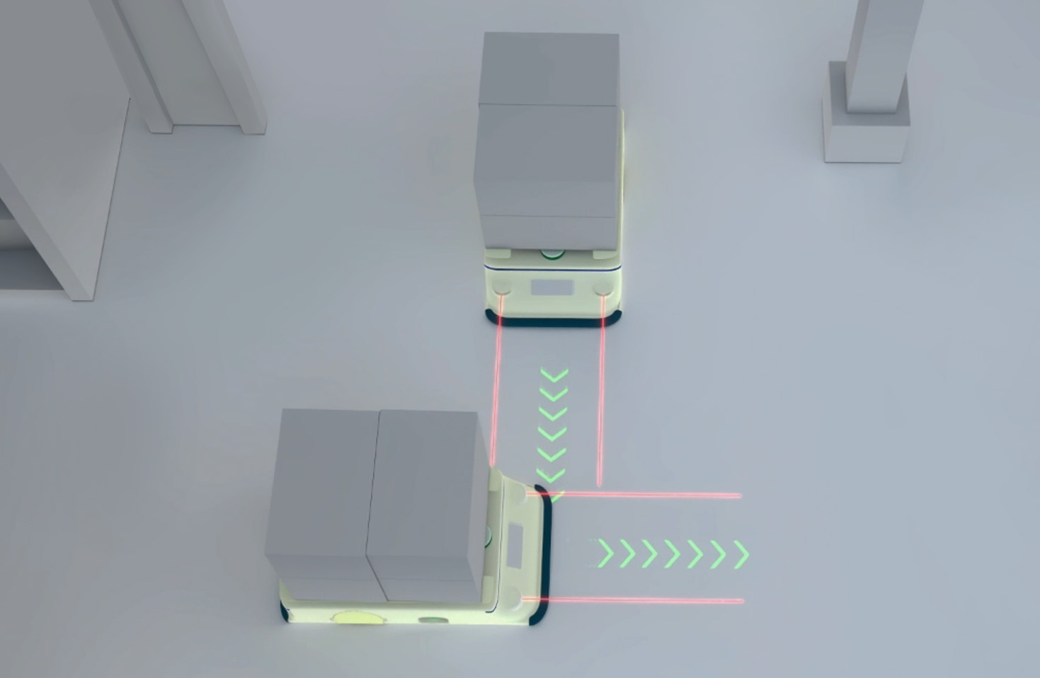
Practical application of this formula is extensive. In system design, it helps select the appropriate sensor for a required working range. A sensor with a very small divergence angle might have insufficient reflective area at long distances, resulting in a weak signal. Conversely, a large divergence angle at a short range might illuminate too large an area, potentially causing interference from background objects.
In alignment and installation, understanding the impact of the angle of incidence (α) is key. Misalignment can drastically change the effective reflective area, leading to inconsistent readings or sensor failure. Technicians use this knowledge to ensure targets are presented within the sensor's specified angular tolerance.
Furthermore, this formula interacts with the target's surface properties, encapsulated by its reflectance (ρ). The total optical power received (P_rec) is a function of the emitted power (P_emit), the reflectance, and the geometric coupling defined by the reflective area and the receiver's solid angle: P_rec ∝ P_emit * ρ * (A_ref / d²). This complete model allows for predicting whether a dark (low ρ) or small target will generate a detectable signal.
Limitations must be acknowledged. The formula assumes ideal diffuse reflection. Specular (mirror-like) surfaces will not follow this model and require a different approach. Environmental factors like ambient light, dust, or humidity are not accounted for but significantly affect real-world performance. Sensor specifications, such as receiver sensitivity and lens design, ultimately determine how the theoretical reflective area translates into an electrical signal.
In conclusion, the reflective area formula provides a foundational geometric model for laser sensor operation. By quantifying how distance, beam angle, and surface orientation affect the light signal returned to the sensor, it enables informed decisions in selection, integration, and troubleshooting. Mastery of this concept moves beyond simply connecting a device to truly engineering a reliable and robust sensing solution. It bridges the gap between theoretical optics and the practical demands of modern automation, ensuring that these critical components perform as expected in diverse and challenging environments.