Installing a laser sensor correctly is crucial for ensuring its accuracy, reliability, and longevity. Whether you're setting up a sensor for industrial automation, robotics, security, or a DIY project, following a systematic approach will save you time and prevent costly errors. This guide provides comprehensive instructions applicable to a wide range of laser sensors, including distance, positioning, and safety scanners.
Pre-Installation Planning and Safety
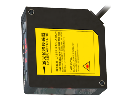
Before touching any equipment, thorough planning is essential. First, consult the sensor's datasheet and user manual. Identify key specifications: required voltage (e.g., 12-24V DC), output signal type (analog, digital, PWM, serial communication like RS-485), and the sensing range. Gather all necessary tools: appropriate screwdrivers, wrenches, a multimeter for voltage checks, mounting brackets, and cables.
Safety is paramount. Always disconnect power to the entire system before starting. Laser sensors, especially Class 2 or higher, can be harmful to eyes. Never look directly into the laser beam or point it towards people. Use appropriate personal protective equipment if required by your work environment.
Step 1: Mounting the Sensor
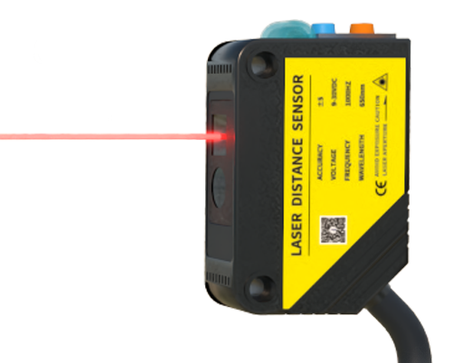
Choose a stable, vibration-free mounting location. The sensor must be firmly secured to prevent misalignment from shocks or machine vibrations. Use the provided brackets or a suitable custom fixture. Ensure the mounting surface is clean and flat.
Critical consideration: alignment. The sensor's beam must strike the target object correctly. For reflective surfaces, you may need to mount the sensor at an angle to avoid direct specular reflection back into the receiver, which can cause false readings. For through-beam sensors (separate transmitter and receiver), precise alignment is absolutely critical. Use alignment tools if provided, or carefully adjust until the receiver's alignment indicator confirms a strong signal.
Step 2: Electrical Connections
Incorrect wiring is a leading cause of sensor failure. Follow the wiring diagram in the manual precisely. Typical connections include:
* Power Supply (V+/V-): Connect to a stable DC power source within the specified range. Use the multimeter to verify voltage before connecting the sensor.
* Output Wires: These carry the sensor's signal. Common configurations are NPN (sinking) or PNP (sourcing). Ensure your controller (PLC, Arduino, etc.) is compatible. Connect the output wire to the correct input channel.
* IO-Link or Communication Wires: For smart sensors, connect the data line as specified.
Use shielded cables for longer runs or in electrically noisy environments (near motors, VFDs). Connect the shield to ground at only one end, typically the controller side, to prevent ground loops. Secure all connections with cable glands or strain relief to prevent wires from being pulled loose.
Step 3: Configuration and Calibration
Many laser sensors require initial setup. This might involve:
* Teaching/Setting Reference Points: For distance sensors, you may need to "teach" the near and far limits of your measurement range.
* Adjusting Sensitivity: Set the detection threshold to reliably see your target while ignoring background objects or dust.
* Configuring Output Behavior: Define if the output is on when an object is detected or when it is absent.
Use the sensor's built-in buttons, DIP switches, or dedicated configuration software. For complex setups, software provides a much clearer interface for setting parameters like response time, averaging filters, and output logic.
Step 4: Testing and Validation
After installation and configuration, apply power. Perform thorough testing before integrating the sensor into the full system operation.
1. Functional Test: Move the target object through the entire sensing range. Verify the output switches states reliably (observe an LED on the sensor or a diagnostic input on your controller).
2. Accuracy Test: Measure known distances or positions. Compare the sensor's readout (via its display or software) against a physical measurement. Check for consistency and repeatability.
3. Robustness Test: Introduce potential real-world interferences. Check if ambient light, temperature changes, or nearby reflective surfaces affect performance. Ensure cables are not near sources of electrical noise.
Step 5: Finalization and Documentation
Once testing is complete, finalize the installation. Secure all cable runs with cable ties. Ensure the sensor lens is clean and free from obstructions. Apply any protective covers if operating in harsh environments.
Document your work. Note the sensor's model, serial number, installed location, wiring diagram used, and any specific configuration settings. This is invaluable for future troubleshooting, maintenance, or replacement.
Common Troubleshooting Tips
* No Power/No Indicator Light: Check power supply voltage and polarity. Verify fuse integrity.
* Intermittent or Unstable Readings: Check for loose connections, poor alignment, or electrical interference. Verify the target surface properties; dark, absorbent, or transparent materials can be challenging.
* Sensor Triggers Erratically: Look for environmental factors like dust, steam, or highly reflective objects in the background. Adjust the sensitivity or use a sensor with background suppression technology.
By meticulously following these steps—planning, safe mounting, correct wiring, careful configuration, and rigorous testing—you ensure your laser sensor installation forms a solid foundation for your application's success. Regular inspection and lens cleaning will maintain optimal performance for years to come.