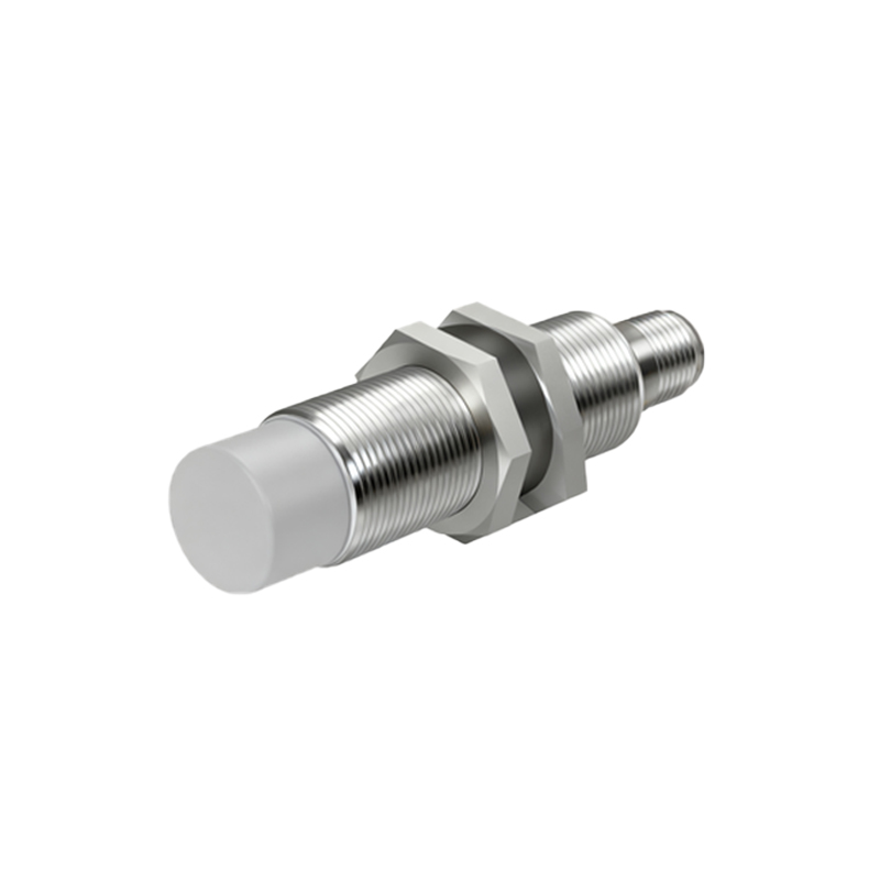
Proximity sensors are fundamental components in modern automation, robotics, and industrial control systems. Their ability to detect the presence or absence of an object without physical contact makes them invaluable. However, their correct operation hinges entirely on a proper understanding of their pinout—the configuration and function of each electrical connection pin. Miswiring can lead to sensor failure, inaccurate readings, or damage to connected controllers like PLCs. This guide demystifies the common pin configurations for different types of proximity sensors, focusing on practical connection knowledge.
While designs vary by manufacturer and model, most industrial proximity sensors share a common logical pinout structure. The most critical distinction is between 2-wire, 3-wire, and 4-wire (or sometimes 5-wire) sensors. Two-wire sensors are the simplest, integrating directly into the power supply line. They act as a switch, but their leakage current is a key consideration when connecting to PLC inputs. The more prevalent and versatile type is the 3-wire sensor. Here, the pinout typically consists of three distinct wires: brown (or red) for the positive supply voltage (V+), blue for the common negative or ground (0V), and black (or white) for the output signal. This separation of power and signal lines allows for more stable operation and compatibility with different output types.
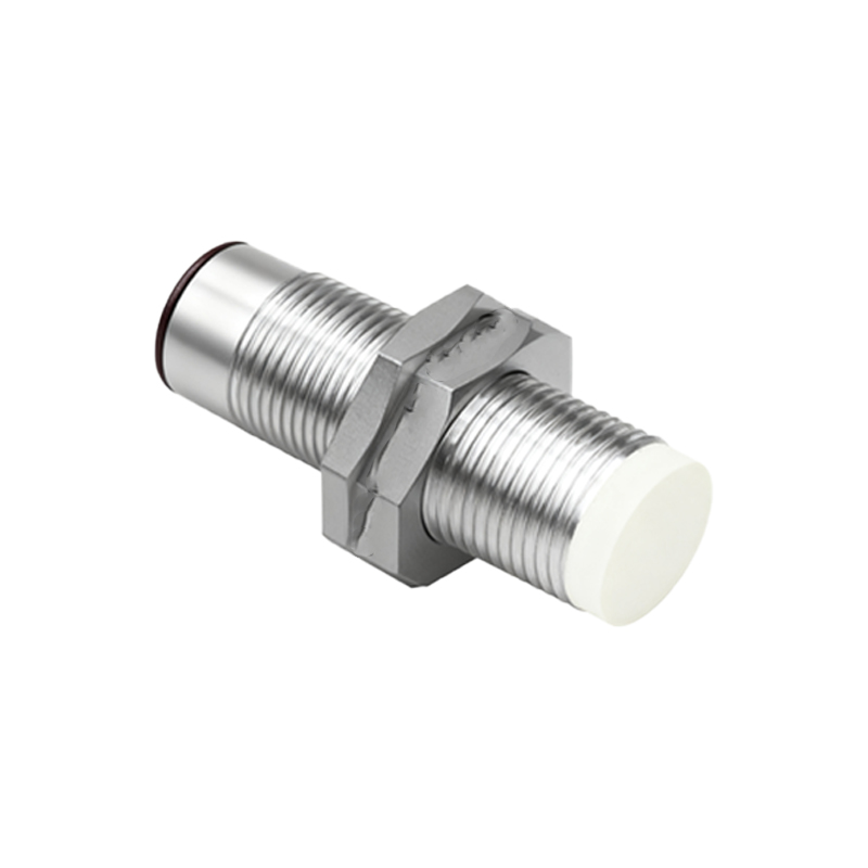
The output type defines the function of the signal pin. For a 3-wire sensor, the black wire's behavior depends on whether it is configured as an NPN (sinking) or PNP (sourcing) output. An NPN output sensor connects the load (e.g., a PLC input) between the signal wire and the positive supply. When activated, the NPN transistor inside the sensor sinks current, pulling the signal line voltage low towards 0V. Conversely, a PNP output sensor connects the load between the signal wire and ground. When activated, its internal PNP transistor sources current, bringing the signal line voltage high towards V+. Confusing NPN and PNP wiring is a common installation error. Always consult the sensor's datasheet; the color code is a guideline, but the model number defines the true electrical behavior.
Four-wire sensors often incorporate two separate outputs, commonly one NPN and one PNP, or sometimes a Normally Open (NO) and a Normally Closed (NC) output from the same sensing element. The pinout expands to include, for example, brown (V+), blue (0V), black (NPN output), and white (PNP output). This provides flexibility for interfacing with different control system standards. Some advanced sensors or ultrasonic models may have additional pins for analog output (e.g., 0-10V or 4-20mA), teach-in functions, or IO-Link digital communication, which carries both power and bidirectional data over a standard 3-wire interface.
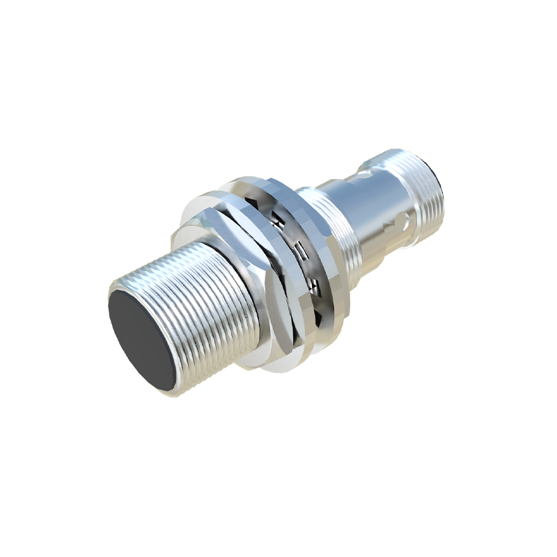
Correct wiring procedure is essential. First, always disconnect power. Identify the sensor type and voltage range (commonly 10-30V DC). Connect the power supply wires (brown to +V, blue to -V) first. Then, connect the output signal wire to the designated input point on your controller. For a DC sensor, ensure the controller input type (sinking or sourcing) matches the sensor output type (NPN or PNP) to form a complete circuit. Using a shielded cable and grounding the shield at the controller end is recommended for electrically noisy environments to prevent false triggering. Finally, verify operation by bringing a target material within the sensor's specified sensing range and checking the controller's input status indicator.
Understanding the pinout is not just about connecting colored wires. It involves comprehending the electrical logic that ensures reliable signal transmission. A correctly wired sensor provides a clean, swift transition of the output signal state, enabling precise timing and control in automated processes. Whether you are integrating a simple inductive sensor for metal detection or a complex capacitive sensor for liquid level control, starting with a solid grasp of the connection pins is the first step toward a robust and reliable sensing solution.