Introduction to Photoelectric Sensors in Bag Coding
In modern packaging lines, accurate and reliable coding on bags is essential for traceability, branding, and compliance. Photoelectric sensors play a critical role in detecting the presence, position, and motion of bags before inkjet or laser coders apply marks. Unlike mechanical limit switches, these sensors offer non-contact detection, reducing wear and maintenance. For engineers, selecting the right sensor type—diffuse, retro-reflective, or through-beam—depends on bag material, opacity, and surface finish. This article focuses on technical considerations for integrating photoelectric sensors into bag coding systems.
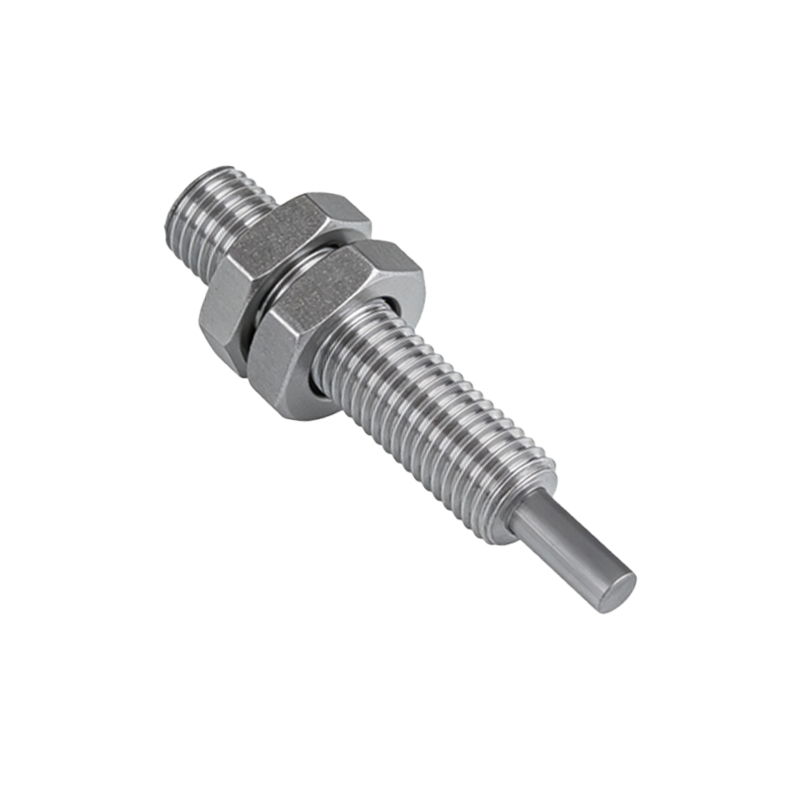
Sensor Selection Criteria for Bag Materials
Bag materials vary widely, from transparent PE films to opaque kraft paper. For transparent bags, retro-reflective sensors with polarized filters are recommended to avoid false triggers from shiny surfaces or background reflections. Diffuse sensors with background suppression work best for opaque or textured bags, as they can detect edges regardless of color variation. Through-beam sensors offer the longest range and highest reliability for dusty environments, but they require alignment of emitter and receiver on both sides of the line. Always verify the sensor’s response time (typically< 1 ms) to match coder speed, especially for high-speed lines exceeding 120 bags per minute.
Installation and Alignment Best Practices
Proper sensor placement ensures consistent bag detection. Mount the sensor at a height where the bag’s leading edge triggers it just before the coding position. For retro-reflective models, install the reflector at least 100 mm behind the bag path to avoid interference from bag flutter. Use adjustable brackets to fine-tune the sensing angle; a misalignment of even 2 degrees can cause missed triggers. In high-vibration environments, secure cables with strain relief connectors and use shielded twisted-pair wiring to prevent electromagnetic interference from nearby motors or coders. Calibrate sensitivity using the teach-in function, setting the threshold to distinguish between bag presence and background noise.
Handling Common Industrial Challenges
Dust, static, and bag jams are frequent issues. Install air blow-off nozzles directed at the sensor lens to keep it clean in dusty facilities. For static-prone bags, use ionizing bars near the sensor to reduce false detections caused by electrostatic discharge. If bags jam, implement a redundant sensor pair: one for bag detection and one for jam detection. Software logic can then pause the coder and trigger an alarm. Additionally, consider sensors with IO-Link communication for real-time diagnostics and parameter adjustment, which simplifies troubleshooting in distributed control systems.
Integration with Coding Equipment
Connect the sensor’s output (NPN or PNP, depending on PLC input) to the coder’s trigger input via a dedicated digital I/O module. Use a pulse stretcher if the sensor signal is shorter than the coder’s minimum trigger pulse width (e.g., 10 ms). For dual-head coders printing on both sides of the bag, synchronize two sensors via a master-slave configuration. Test the system with a sample run, using a oscilloscope to verify signal timing and ensure the coder fires exactly when the bag is at the print window. Document the sensor’s rated ambient temperature and IP rating (e.g., IP67) to guarantee operation in washdown or freezer environments.
Maintenance and Troubleshooting Tips
Schedule weekly lens cleaning with a soft, lint-free cloth and isopropyl alcohol. Check alignment every 500 operating hours. If misreads increase, first inspect the sensing surface for scratches or fogging. Use a multimeter to measure sensor supply voltage (typically 10-30 VDC) and output current. For intermittent issues, review the PLC program for scan cycle delays. Replace sensors with matched models from the same manufacturer to avoid response time or beam angle discrepancies. Keep spare sensors and reflectors on hand to minimize downtime.