Introduction to Photoelectric Sensors and Raspberry Pi
Photoelectric sensors are widely used in industrial automation for object detection, counting, and positioning. These sensors emit a beam of light (typically infrared) and detect changes in the reflected or interrupted beam. The Raspberry Pi, a low-cost single-board computer, offers GPIO pins and I2C/SPI interfaces to interface with such sensors. This guide walks you through the hardware setup, wiring, and Python code to control a photoelectric sensor for reliable detection in engineering projects.
Hardware Requirements and Wiring
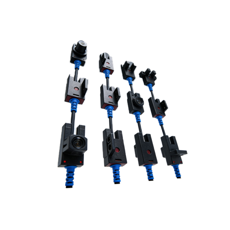
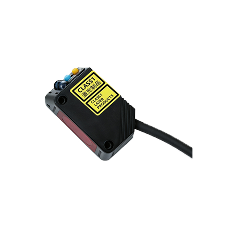
To begin, you need a Raspberry Pi (any model with GPIO), a photoelectric sensor (e.g., E3F-DS10C4 NPN type), a breadboard, jumper wires, and a 10kΩ resistor. Connect the sensor’s brown wire to the Pi’s 5V pin, blue wire to GND, and black wire (output) to a GPIO pin (e.g., GPIO17). Use the 10kΩ resistor as a pull-up between the output pin and 3.3V to ensure stable logic levels. Verify the sensor’s datasheet for voltage and current ratings to avoid damaging the Pi.
Configuring GPIO Pins and Enabling I2C/SPI
Enable the necessary interfaces via the Raspberry Pi configuration: runsudo raspi-config, navigate to Interface Options, and enable I2C or SPI if your sensor uses these protocols. For digital output sensors, only the GPIO library is needed. Install the required Python libraries:
sudo apt update && sudo apt install python3-rpi.gpio
For analog sensors, you may need an ADC like the MCP3008. Ensure you have root permissions to access the GPIO.
Python Code for Sensor Reading
Here is a minimal Python script to read the sensor state and print detection events:
``python
import RPi.GPIO as GPIO
import time
SENSOR_PIN = 17
GPIO.setmode(GPIO.BCM)
GPIO.setup(SENSOR_PIN, GPIO.IN, pull_up_down=GPIO.PUD_UP)
try:
while True:
if GPIO.input(SENSOR_PIN) == GPIO.LOW:
print("Object detected")
else:
print("No object")
time.sleep(0.1)
except KeyboardInterrupt:
GPIO.cleanup()
`
This code uses a pull-up resistor internally for stability. Adjust the pin number and logic level (LOW vs HIGH) based on your sensor’s output type (NPN or PNP).
Calibration and Noise Filtering
Industrial environments introduce electrical noise. Implement a debounce routine by checking the sensor state multiple times over 10ms intervals. For example, use a simple moving average filter:
`python
def read_sensor_stable(pin, samples=5, delay=0.002):
readings = [
for _ in range(samples):
readings.append(GPIO.input(pin))
time.sleep(delay)
return 1 if sum(readings) > samples/2 else 0
`
This reduces false triggers from vibration or EMI. Adjust the threshold based on your sensor’s response time.
Advanced Integration with Industrial Protocols
For real-world applications, integrate the sensor data with Modbus TCP or MQTT for remote monitoring. Use libraries likepymodbus orpaho-mqtt to send detection events to a PLC or SCADA system. Example MQTT publish:
`python
import paho.mqtt.client as mqtt
client = mqtt.Client()
client.connect("broker_address", 1883)
while True:
state = GPIO.input(SENSOR_PIN)
client.publish("sensor/photoelectric", str(state))
time.sleep(1)
``
This enables cloud-based analytics or automated responses in a factory network.
Safety and Best Practices
Always use current-limiting resistors and isolate the Pi from high-voltage sensors with optocouplers. Test the sensor in a controlled environment before deployment. For long cable runs, use twisted-pair shielded wiring to reduce noise. Document your wiring and code for maintenance. Consider using a real-time operating system or dedicated microcontroller for time-critical tasks.