Introduction to Retroreflective Photoelectric Sensors
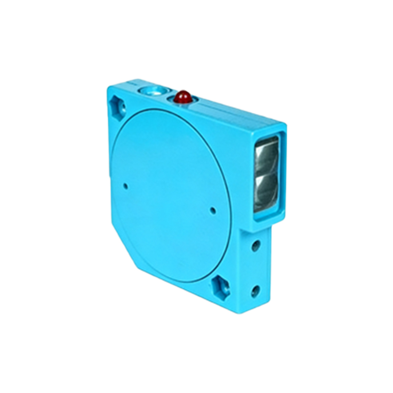
Retroreflective photoelectric sensors are a staple in industrial automation, offering reliable object detection across conveyors, packaging lines, and material handling systems. Unlike through-beam sensors that require separate transmitter and receiver units, retroreflective sensors combine both components in a single housing. They emit a modulated beam of light toward a specially designed reflector, which returns the beam to the sensor. When an object interrupts the light path, the sensor detects the break and triggers a response. The reflector, often a corner-cube prism or a reflective tape array, is the critical component ensuring consistent signal return, even in dusty or vibrating environments.
How the Reflector Works in a Retroreflective System
The reflector in a retroreflective sensor does not simply mirror light like a standard mirror. Instead, it uses a principle called retroreflection, where light is returned directly to the source regardless of the incident angle. This is achieved through microprismatic structures or glass beads embedded in the reflector surface. For example, a corner-cube reflector consists of three mutually perpendicular surfaces that reflect incoming light back along its original path. This property minimizes alignment requirements, making installation quicker and more forgiving than through-beam systems. The reflector must be kept clean and undamaged, as contamination or scratches can degrade performance by reducing the intensity of the returned signal.
Key Specifications for Selecting a Reflector
When choosing a reflector for your retroreflective sensor, consider the following parameters: size, material, operating distance, and environmental resistance. Larger reflectors provide a wider detection zone and longer sensing ranges, but may increase cost and mounting footprint. Common materials are acrylic, polycarbonate, or glass, each offering different transmissivity and durability. For harsh industrial settings, choose a reflector with high UV stability and a robust housing that withstands temperature extremes from -20°C to 70°C. Also verify the reflector’s compatibility with the sensor’s wavelength, typically 660 nm (red light) or 850 nm (infrared). A mismatch can cause unreliable detection.
Installation and Alignment Best Practices
Proper alignment is essential for optimal sensor performance. Mount the reflector so that its surface is perpendicular to the sensor’s optical axis, with a tolerance of +/- 5 degrees. Use a laser pointer or the sensor’s alignment indicator to ensure the beam center hits the reflector’s active area. Avoid placing the reflector near reflective surfaces, such as shiny metal walls or glass, which can cause false signals due to stray reflections. In high-vibration environments, secure the reflector with locking washers or anti-vibration mounts. Periodically inspect the reflector for dust, oil, or condensation, and clean it with a soft cloth and isopropyl alcohol if needed.
Troubleshooting Common Reflector Issues
If your sensor experiences false triggers or no detection, inspect the reflector first. A common issue is misalignment due to thermal expansion or mechanical drift. Realign the reflector and check the mounting brackets for looseness. Another problem is reflector degradation, such as yellowing from UV exposure or cracking from thermal cycling. Replace any reflector showing signs of wear. For long-range applications, ensure the sensor’s excess gain is sufficient to overcome signal loss from dust or fog. If the reflector is too small for the sensing distance, upgrade to a larger model or switch to a polarized retroreflective sensor for use with shiny targets.
Maintenance Tips for Long-Term Reliability
To extend the life of your retroreflective sensor system, implement a routine maintenance schedule. Clean the reflector weekly in dusty environments using a lint-free cloth. Check for physical damage, such as chips or warping, and replace the reflector immediately if any defects are found. Store spare reflectors in a cool, dry place away from direct sunlight to prevent premature aging. Additionally, verify that the sensor’s indicator LED shows a stable red or green signal, depending on the model, indicating consistent return from the reflector. Document inspection findings in a log to track degradation trends over time.