Understanding Photoelectric Sensor Basics
Photoelectric sensors are essential components in industrial automation, used for detecting objects, distances, and material presence without physical contact. These sensors emit a light beam (typically infrared, visible red, or laser) and measure changes in the reflected or interrupted light to trigger output signals. For reliable operation, correct wiring is critical—especially in harsh electrical environments with noise, vibration, or temperature extremes.
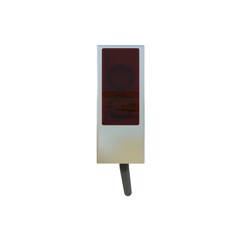
Identifying Sensor Types and Output Configurations
Before wiring, determine your sensor type: through-beam, retro-reflective, or diffuse. Each has different wiring needs. Also, check the output type—NPN (sinking) or PNP (sourcing). NPN outputs switch the load to ground, while PNP outputs switch to the positive supply. Most sensors have three wires: brown (V+), blue (V-), and black (output). Some include a white wire for test or alarm functions. Always verify the datasheet for your specific model.
Wiring a DC Three-Wire Photoelectric Sensor
Connect the brown wire to the positive DC supply (typically 10-30 VDC). Connect the blue wire to the DC common (0V). The black wire is the output: for NPN, connect to a PLC input module's sinking terminal; for PNP, connect to a sourcing terminal. Use a pull-up or pull-down resistor if needed for noise immunity. Ensure power supply is within the sensor's rated voltage range and has sufficient current capacity.
Wiring an AC/DC Two-Wire Photoelectric Sensor
Two-wire sensors are simpler but require careful attention to voltage drop and leakage current. Connect one wire to the supply line (AC or DC) and the other to the load. The load must be in series with the sensor. For DC, ensure the supply polarity is correct. Leakage current (typically 0.5-1.5 mA) may cause false triggering in high-impedance loads. Use a load resistor in parallel if needed.
Wiring with Shielded Cables for Noise Reduction
In industrial settings, electromagnetic interference (EMI) can disrupt sensor signals. Use shielded twisted-pair cables for long runs (over 10 meters). Connect the shield drain wire to the earth ground at the controller end only, not at both ends, to avoid ground loops. Keep sensor wires away from high-voltage power cables and motor drives. For sensitive applications, install ferrite beads on the supply and output lines.
Testing and Troubleshooting the Wiring
After wiring, power on the system without load first. Use a multimeter to check voltage at the sensor terminals: brown to blue should read nominal supply voltage. Activate the sensor by interrupting the light beam (for through-beam or retro-reflective) or by placing an object in front (for diffuse). Verify the output voltage at the black wire: for NPN, it should drop to near 0V when triggered; for PNP, rise to near supply voltage. If the output is erratic, check for loose connections, incorrect polarity, or ground loops. For sensors with LED indicators, observe their behavior—steady on or off indicates proper operation.
Safety Considerations and Best Practices
Always disconnect power before wiring or modifying connections. Use fuses or circuit breakers rated for the sensor's maximum current to prevent damage from shorts. Follow lockout/tagout procedures when working on live systems. For wet or dusty environments, select sensors with IP67 or higher ratings and use sealed connectors. Document all wiring details for future maintenance.