Introduction to Photoelectric Sensors for Speed Monitoring
In modern industrial automation, precise speed measurement is critical for process control, quality assurance, and equipment protection. Photoelectric sensors offer a non-contact, reliable solution for rotational speed monitoring. These sensors utilize a light beam—typically infrared or visible—emitted toward a reflective target or through an encoder disk. When the rotating shaft interrupts or reflects the light, the sensor generates a pulse signal. By counting these pulses over a defined time period, engineers can calculate revolutions per minute (RPM) with high accuracy. Key advantages include immunity to mechanical wear, fast response times, and compatibility with harsh environments. Common applications include motor feedback, conveyor belt speed control, and turbine monitoring.
Selecting the Right Photoelectric Sensor Type
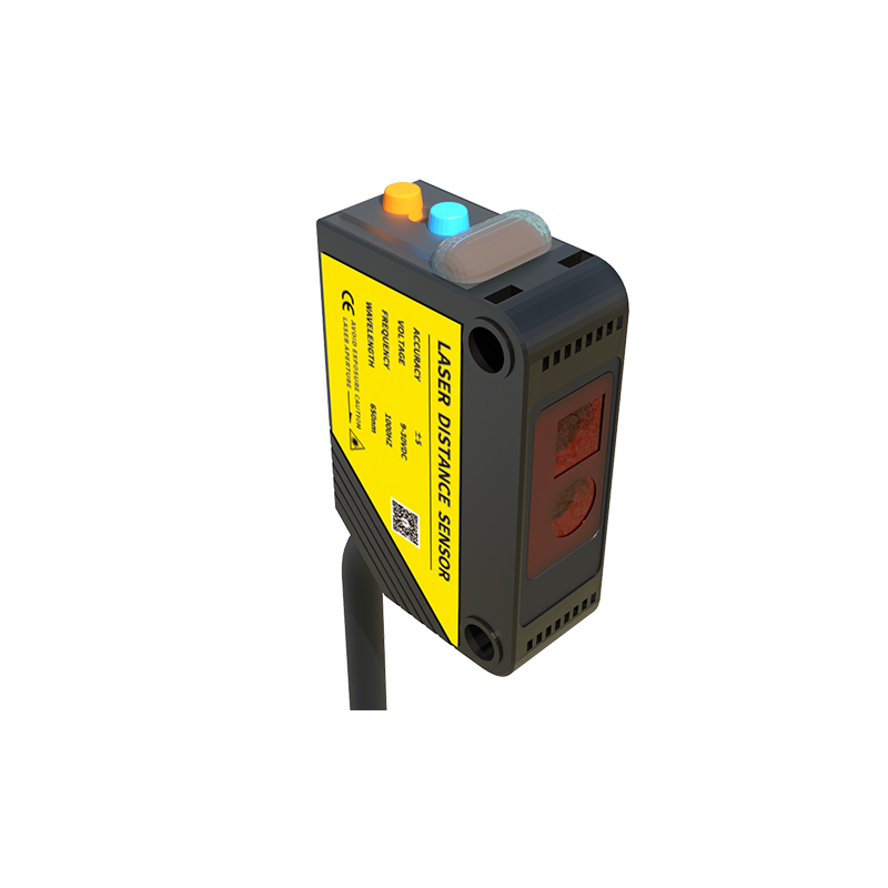
Choosing the appropriate sensor depends on the target characteristics and operating conditions. For clear or highly reflective surfaces, a polarized retro-reflective sensor is recommended to avoid false triggers. Through-beam sensors provide the longest range and highest reliability in dusty environments, as they consist of separate emitter and receiver units. Diffuse mode sensors are suitable for short-range detection on non-reflective surfaces. When measuring high-speed rotation, engineers must consider the sensor's switching frequency. A sensor with a fast response time (e.g., 0.1 ms or less) can reliably capture pulses at speeds exceeding 10,000 RPM. Additionally, ensure the sensor's output type (NPN, PNP, or push-pull) matches the controller input.
Installation Best Practices for Accurate RPM Readings
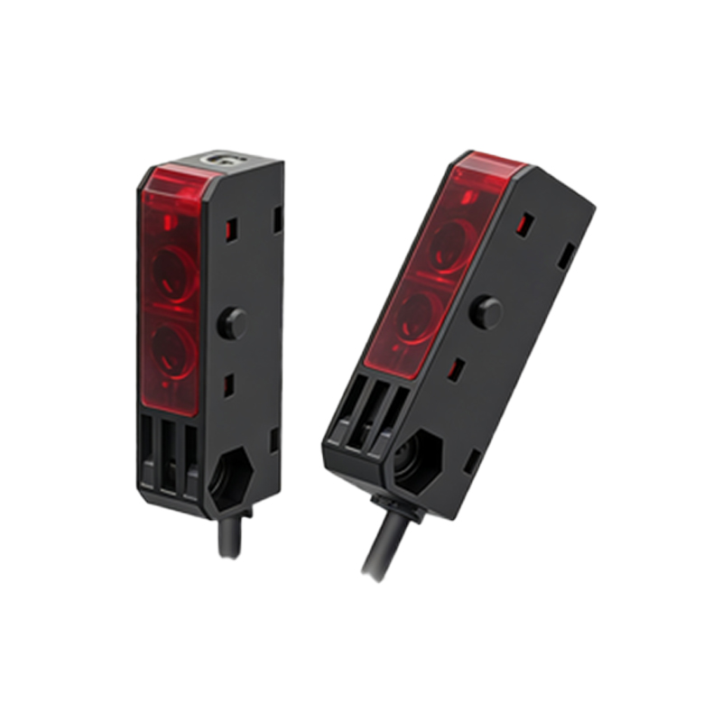
Proper mounting and alignment are essential for consistent performance. Mount the sensor perpendicular to the rotating target to minimize angular errors. The sensing distance should be maintained within the specified range, typically 10–50 mm for standard models. Use a slotted disk or tape with alternating reflective and non-reflective segments for pulse generation. The segment width must be larger than the sensor's spot diameter to avoid signal overlap. Shield sensor cables from high-voltage power lines and use twisted-pair wiring to reduce electromagnetic interference. For applications with vibration, secure the sensor with locking brackets and consider using a flexible coupling.
Signal Processing and Speed Calculation Methods
Once pulses are acquired, the speed can be calculated using either frequency or period measurement. The frequency method counts pulses over a fixed time window (e.g., 1 second) and multiplies by 60 to obtain RPM. This is effective for medium to high speeds but loses accuracy at low RPM due to fewer pulses per sampling period. The period method measures the time between consecutive pulses and is ideal for low-speed applications. Modern PLCs and frequency-to-analog converters can perform these calculations in real-time. For critical systems, use a dedicated tachometer module with built-in filtering to remove noise-induced false pulses. Always calibrate the system by comparing sensor readings with a reference tachometer.
Troubleshooting Common Issues in Photoelectric Speed Sensing
Common problems include intermittent signals, false triggers, and complete loss of detection. Intermittent signals often result from misalignment or contamination on the sensor lens or target. Clean lenses with isopropyl alcohol and check for scratches. False triggers may occur from ambient light sources—use modulation-based sensors that reject constant light. For high-vibration environments, secure all connections and apply dielectric grease to prevent corrosion. If the sensor fails to detect at high speed, verify that the sensor's switching frequency exceeds the pulse rate. Upgrade to a sensor with a higher maximum operating frequency, such as a fiber-optic amplifier pair. Regular maintenance and spare sensor stocking reduce downtime.