Introduction to Through-Beam Photoelectric Sensors
Through-beam photoelectric sensors are a cornerstone of industrial automation, offering unparalleled reliability for object detection over long distances. These sensors consist of a separate emitter and receiver, with the emitter sending a continuous beam of light directly to the receiver. When an object interrupts this beam, the sensor triggers an output signal. This design ensures high immunity to ambient light, dust, and other environmental factors, making through-beam sensors ideal for harsh manufacturing environments.

Key Specifications of the LS3C Sensor
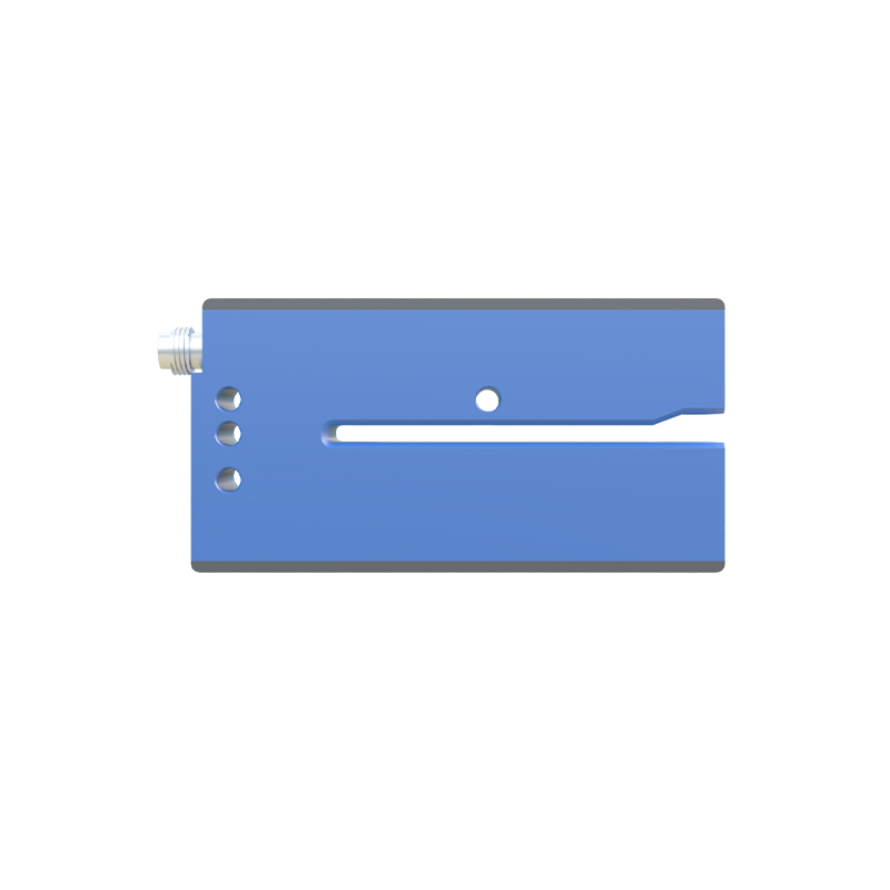
The LS3C is a specialized through-beam photoelectric sensor, commonly used in conveyor systems, packaging lines, and material handling equipment. It operates at a typical sensing distance of up to 15 meters, depending on the model and application conditions. The LS3C features a modulated infrared light source, which minimizes interference from ambient light and enhances detection accuracy. Its response time is typically under 1 millisecond, allowing for high-speed object counting and positioning. The sensor is rated for an IP67 enclosure, ensuring protection against dust ingress and temporary water immersion.
Installation and Alignment Best Practices
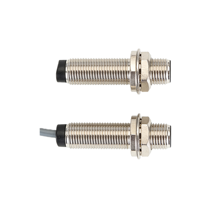
Proper installation of the LS3C is critical for optimal performance. Begin by mounting the emitter and receiver on rigid, vibration-free surfaces, ensuring they are directly opposed and aligned within 5 degrees of optical axis. Use laser alignment tools for precise positioning in long-range setups. The sensor’s built-in alignment indicator, often an LED, assists in fine-tuning the beam path. Avoid placing the sensor near reflective surfaces, such as glossy metals or glass, as these can cause false triggering. For outdoor applications, consider adding sunshades to reduce direct sunlight interference.
Electrical Connectivity and Output Configurations
The LS3C typically supports a universal power supply range of 10-30 VDC, with reverse polarity protection. It offers two primary output types: NPN (sinking) and PNP (sourcing), both available as normally open (NO) or normally closed (NC). For integration with programmable logic controllers (PLCs), select the output type matching your controller’s input module. The sensor includes a short-circuit protection circuit, preventing damage from accidental wiring faults. A common wiring scheme uses a 4-wire cable: brown for power (V+), blue for ground (V-), black for output, and white for a secondary function (e.g., test input or selectable output mode).
Performance in Challenging Environments
The LS3C excels in dusty, humid, or high-vibration environments. Its modulated light source and synchronous detection circuitry filter out ambient light fluctuations from welding arcs, sunlight, or nearby machines. For applications involving transparent objects, such as glass bottles or clear plastic films, the LS3C’s infrared wavelength ensures reliable detection without false signals from light transmission. In foggy or steam-filled conditions, the sensor’s high optical power maintains beam integrity, though condensation on the lenses may require periodic cleaning or use of heated housings.
Troubleshooting Common Issues
If the LS3C fails to detect objects, first verify alignment. Check for lens contamination using a soft, lint-free cloth and isopropyl alcohol. Confirm the power supply voltage is within the rated range and that wiring connections are secure, especially for ground and output terminals. If the sensor triggers erratically, inspect for reflective objects in the beam path or nearby electromagnetic interference from variable frequency drives (VFDs). Adjust the sensitivity potentiometer, if available, to fine-tune the detection threshold. For persistent issues, replace the emitter or receiver unit, as internal component degradation can occur over extended use.
Maintenance and Longevity Tips
Regular maintenance extends the LS3C’s operational life. Schedule quarterly inspections for lens cleanliness, connector tightness, and cable integrity. In corrosive environments, apply dielectric grease to electrical contacts to prevent oxidation. Monitor ambient temperature; while the LS3C operates between -25°C and +55°C, thermal stress near the upper limit can degrade internal components. Replace the unit every 3-5 years in continuous-duty applications, as the LED emitter’s output gradually diminishes. Documentation of alignment and performance benchmarks aids in predictive maintenance planning.