Understanding Photoelectric Sensors in Automated Soldering
Photoelectric sensors are critical components in modern automatic soldering machines, ensuring precision, reliability, and safety. These sensors use light beams to detect the presence, position, or absence of components, such as PCBs, pins, or wires, without physical contact. In the soldering process, they prevent misalignment, double-feeding, or jamming, which can lead to cold joints, bridging, or damage to delicate parts. Common types include through-beam, retro-reflective, and diffuse sensors, each suited for specific applications like detecting transparent materials or long-range positioning.
Key Selection Criteria for Soldering Environments
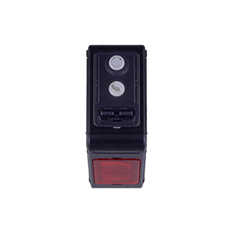
Choosing the right photoelectric sensor for soldering requires careful evaluation of environmental factors. High temperatures, fumes, and potential splatter from molten solder can degrade sensor performance. Engineers should prioritize sensors with IP67 or higher ratings for dust and moisture resistance, and with built-in temperature compensation. Background suppression and narrow beam angles help avoid false triggers caused by reflective surfaces or nearby components. For instance, in a high-speed soldering station, a laser-based diffuse sensor with a focused spot ensures accurate detection of tiny SMD pins.
Integration and Wiring Best Practices
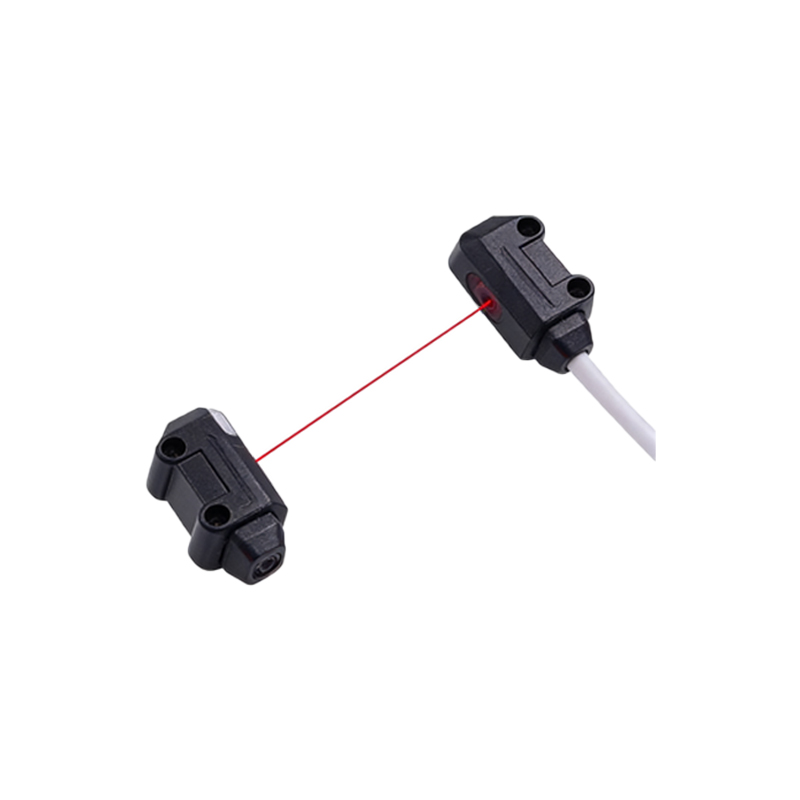
Proper integration is essential to maximize sensor reliability. Use shielded cables and ensure proper grounding to minimize electromagnetic interference (EMI) from nearby motors or heating elements. Place sensors at a safe distance from direct heat sources, and consider using fiber optic sensors for extreme temperature zones. In multi-sensor arrays, synchronize triggering to avoid crosstalk. For example, in a selective soldering machine, a through-beam sensor pair at the conveyor entry can detect incoming PCBs and trigger the soldering nozzle sequence.
Common Failure Modes and Troubleshooting
In field operation, photoelectric sensors may suffer from lens contamination, misalignment, or signal drift. Solder flux and dust accumulate on lenses, reducing light transmission. Regular cleaning with lint-free cloths and isopropyl alcohol is recommended. Misalignment often occurs due to machine vibration; use locking brackets and vibration-dampening mounts. For signal drift, calibrate the sensor threshold after a warm-up period. If you observe intermittent false triggers, check for reflective solder paste residues or fluctuating ambient light.
Maintenance Schedule and Performance Optimization

Establish a preventive maintenance schedule: daily wipe-down of sensor faces, weekly verification of beam alignment, and monthly testing of response time and output stability. Use an oscilloscope to monitor sensor output signal integrity. For advanced optimization, consider sensors with IO-Link communication, allowing remote diagnostics and parameter adjustment. In a high-volume production line, this can reduce downtime by up to 30% by predicting sensor failure before it occurs.
Safety and Compliance Considerations
Always adhere to international safety standards like IEC 61496 for electro-sensitive protective equipment. When using photoelectric sensors for safety-related applications (e.g., machine guard doors), select Type 4 safety-rated sensors with redundant outputs. Ensure the sensor's laser class complies with local regulations (e.g., Class 1 or Class 2). In automated soldering cells, install clear beam guards to prevent accidental exposure to laser beams during maintenance.