Understanding the Structure of Photoelectric Sensor Part Numbers
In the electrical engineering field, photoelectric sensors are critical for automation and control systems. Their part numbers often follow a structured rule table that encodes key specifications such as sensing range, output type, connection method, and housing material. For example, a typical part number like E3Z-T61A might break down into segments indicating through-beam type, NPN output, and pre-wired cable. Mastering these rule tables ensures correct selection, reduces errors, and improves system reliability. Engineers must first identify the sensor family (e.g., E3Z, E3JK, or E3FA) and then decode each alphanumeric segment based on the manufacturer’s datasheet. This approach prevents incompatibility with existing control systems and minimizes downtime during installation.
Decoding the Output Type and Wiring Configuration
The output type segment in the part number rule table is one of the most critical. Common designations include NPN (sinking output) for Japanese-style PLCs, PNP (sourcing output) for European systems, and push-pull for universal compatibility. For instance, in the Omron E3Z series, a digit like "1" often indicates NPN, while "2" denotes PNP. Additionally, connector types are represented by letters: "C" for M8 connector, "D" for M12, or "W" for pre-wired cable. Understanding these codes allows engineers to match the sensor with the PLC input module, avoiding costly rewiring. Always cross-reference the rule table with the system’s voltage requirements (e.g., 12-24 VDC) to ensure operational stability.
Interpreting Sensing Range and Light Source Codes
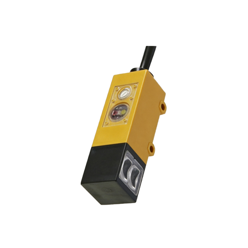
Sensing range and light source are crucial for application-specific performance. In rule tables, numbers often indicate range categories. For example, a range code of "03" might represent 0-3 meters for a through-beam sensor, while "10" could mean 10 meters. Light source codes (e.g., "R" for red LED, "I" for infrared) affect detection accuracy against different target materials and colors. An infrared source is preferred for transparent objects, while a red LED works better for opaque surfaces. Engineers should also check for background suppression features, often marked by a specific letter like "B" in the part number. This ensures the sensor ignores background objects in cluttered environments.
Verifying Environmental Ratings and Housing Materials
Environmental protection is vital for industrial sensors. The rule table typically includes codes for ingress protection (IP) ratings, such as IP67 or IP69K, and housing materials like "S" for stainless steel or "P" for plastic. For harsh environments (e.g., washdown zones), IP69K-rated sensors with stainless steel housing are essential. Additionally, temperature range codes (e.g., "T" for -25 to 55°C) ensure the sensor functions reliably in extreme conditions. When selecting a sensor, always compare the rule table’s environmental codes with the actual working environment to prevent premature failure and maintain safety compliance.
Practical Examples of Part Number Decoding
To solidify understanding, consider a real example: Part number E3Z-T61A-5M. Breaking it down: "E3Z" indicates the series, "T" means through-beam, "6" signifies a 6-meter sensing range, "1" is NPN output, "A" suggests a pre-wired cable, and "5M" indicates a 5-meter cable length. Another example from the E3JK series: E3JK-R4M2. Here, "R4" means retro-reflective with 4-meter range, and "M2" denotes M12 connector with 2-pin. By practicing with these rule tables, engineers can quickly select the correct sensor for applications like conveyor belt detection, object counting, or safety light curtains, ensuring optimal performance and cost efficiency.
Common Pitfalls in Selection and How to Avoid Them
Mistakes often occur when engineers overlook the load current rating or response time in the rule table. For instance, a sensor with a fast response time (e.g., 1 ms) is needed for high-speed counting, but a slow response (e.g., 10 ms) might cause missed detections. Additionally, confusing NPN and PNP outputs can lead to system failures. Always verify the sink/source compatibility by checking the PLC manual. Another common error is ignoring the emission type (e.g., laser vs. LED) for precision applications. Using the rule table as a checklist during selection reduces these risks and enhances system integration.