Introduction to Photoelectric Sensor Wiring
Photoelectric sensors are widely used in industrial automation for detecting objects, measuring distances, and ensuring safety. Proper wiring is critical for reliable operation and to avoid damage to the sensor or control system. This guide provides a step-by-step approach to wiring common types of photoelectric sensors, including through-beam, retro-reflective, and diffuse models. Always refer to the manufacturer’s datasheet for specific pinouts and voltage requirements.
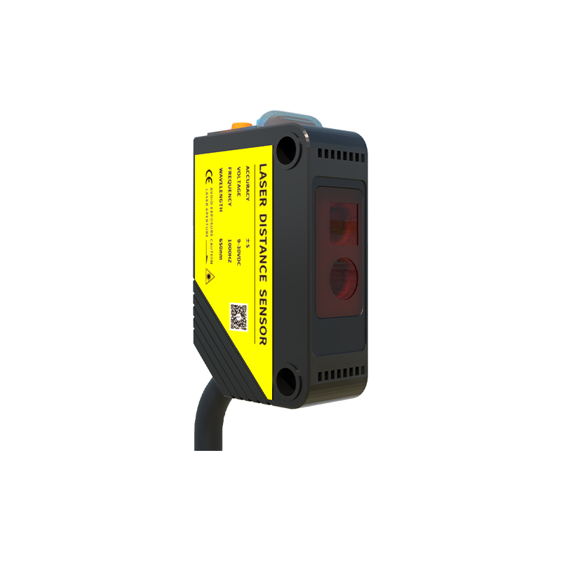
Understanding Sensor Types and Output Configurations
Before wiring, identify your sensor type: through-beam (separate emitter and receiver), retro-reflective (emitter and receiver in one unit with a reflector), or diffuse (emitter and receiver in one unit, detects reflected light from object). Outputs are typically NPN (sinking) or PNP (sourcing), with 3-wire, 4-wire, or 2-wire configurations. NPN outputs switch the load to ground (negative), while PNP outputs switch to positive voltage. Ensure your controller (PLC, relay, or input module) matches the output type.
Wiring a 3-Wire NPN Photoelectric Sensor
A standard 3-wire NPN sensor has three terminals: brown (V+), blue (V-), and black (output). Connect brown to the positive power supply (e.g., 12-24V DC), blue to the negative (ground), and black to the PLC input or load. The load (e.g., relay coil) should be connected between the black wire and the positive supply. When the sensor detects an object, the output transistor turns on, sinking current to ground, activating the load. Use a multimeter to verify voltage levels before final connection.
Wiring a 3-Wire PNP Photoelectric Sensor
For a 3-wire PNP sensor, the wire colors are identical: brown (V+), blue (V-), and black (output). Connect brown to positive, blue to negative, and the load between the black wire and negative (ground). In this case, the output switches positive voltage to the load. Ensure the load’s voltage rating matches the supply. PNP sensors are common in North American systems, while NPN is prevalent in Asian applications. Check your PLC input card specification (sourcing vs. sinking) to avoid mismatches.
Wiring a 4-Wire Photoelectric Sensor
A 4-wire sensor includes two output wires (e.g., normally open and normally closed, or complementary outputs). Typical colors: brown (V+), blue (V-), black (NO output), and white (NC output). Connect brown and blue to power, then use either black or white to control a load, or both for dual-channel monitoring. For example, in a safety application, wire the NC output to a safety relay to detect sensor failure. Always confirm the wiring diagram from the sensor datasheet.
Wiring a 2-Wire AC/DC Photoelectric Sensor
Some photoelectric sensors are 2-wire, handling AC or DC voltage. They have two wires: one for line voltage (e.g., L or +) and one for load (e.g., N or -). The sensor is in series with the load. Connect the sensor in line with the power supply and the load (e.g., motor starter or light). Ensure the load’s current draw is within the sensor’s rated range (e.g., 100mA). A drawback is a small leakage current when off, which may cause false triggering in sensitive circuits; add a bleed resistor if needed.
Testing and Troubleshooting Connections
After wiring, power up the system and test with an object in the detection zone. Use a multimeter to check voltage across the output and ground: for NPN, measure between black and blue (should be ~0V when triggered, supply voltage when not); for PNP, measure between black and brown. Common issues: reversed power polarity (sensor may be damaged), incorrect output type (NPN vs. PNP), or loose connections. If the sensor does not respond, verify the supply voltage and load wiring, and inspect for dirt on the lens.
Safety and Best Practices
Always disconnect power before wiring. Use shielded cables for long distances to prevent electromagnetic interference. Ground the shield at the controller end only. For harsh environments, use sensors with IP67 rating and proper conduit. Refer to local electrical codes (e.g., NEC or IEC) for compliance. Document your wiring for future maintenance.