2026-04-25
Tech Hub
By 创始人
How Photoelectric Sensors Measure Speed: An Engineering Perspective
Introduction to Photoelectric Speed Measurement
Photoelectric sensors are widely used in industrial automation for non-contact speed measurement. They operate by emitting a light beam (usually infrared or visible red) and detecting changes in the reflected or interrupted light caused by a moving target. In speed measurement, these sensors count the number of pulses generated per unit time as a rotating or moving object passes through the detection zone. The key is to convert pulse frequency into linear or rotational speed using precise timing algorithms.
Basic Principle: Pulse Counting and Time Interval
The fundamental method involves attaching a marked disc or a reflective tape to the rotating shaft. As the shaft rotates, each mark or reflective segment passes in front of the sensor, triggering a pulse. By measuring the time interval between consecutive pulses (or counting pulses over a fixed time period), the microcontroller calculates the rotational speed. For example, if a disc has 60 marks and 60 pulses are detected per second, the speed is 1 revolution per second (RPS). The formula is: Speed (RPM) = (Pulse Count × 60) / (Number of Marks × Time in Seconds).
Key Hardware Components for Accuracy
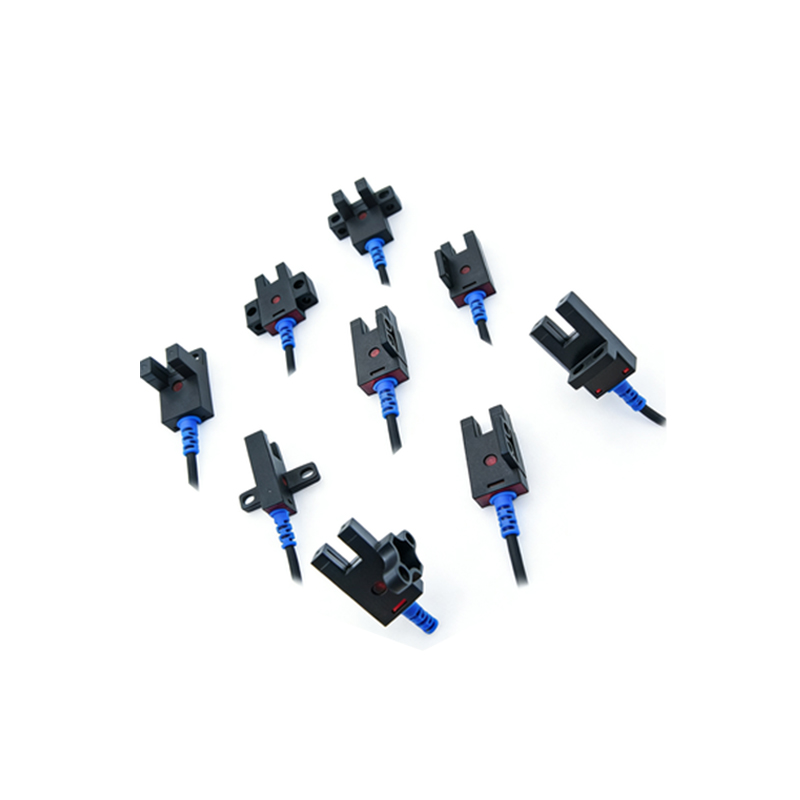
To achieve reliable speed measurement, the sensor selection is critical. Through-beam sensors offer the highest accuracy for clean environments, while retro-reflective sensors are preferred for dusty conditions. The emitter and receiver must be precisely aligned. Additionally, a high-speed counter module or PLC with interrupt capability is required to capture fast pulses without missing counts. For high-speed applications (e.g., >10,000 RPM), sensors with response times below 1 ms are necessary.
Application Example: Conveyor Belt Speed Monitoring
In a conveyor system, a photoelectric sensor is mounted above the belt with reflective markers placed at fixed intervals. As the belt moves, each marker reflects light back to the sensor, generating a pulse. The PLC calculates belt speed by dividing the distance between markers by the time between pulses. This data is used for real-time load balancing and to detect belt slippage. Calibration involves measuring the exact distance between markers and compensating for any environmental light interference.
Common Challenges and Solutions
Environmental factors like dust, vibration, and ambient light can cause false triggering. To mitigate this, use modulated light sensors with built-in filters. For high-vibration environments, fiber optic cables can isolate the sensor from mechanical stress. Additionally, hysteresis settings in the sensor output prevent oscillation near the detection threshold. Regular cleaning of optical surfaces and using shielded cables for signal transmission are best practices.
Advanced Techniques: Phase Difference and Encoder Systems
For dual-channel speed measurement (e.g., for direction detection), two sensors are placed offset by a known phase angle. By comparing the phase shift between the two pulse trains, the system can determine both speed and direction of rotation. This is similar to a quadrature encoder. Alternatively, using a slotted disc with multiple slots allows for higher resolution without increasing the sensor count. Software interpolation can further improve resolution by analyzing pulse edge timing.
Conclusion: Efficiency through Precision
Photoelectric speed measurement is a robust, low-cost solution for industrial automation. By carefully selecting sensor type, mounting, and signal processing hardware, engineers can achieve accuracy within ±0.1% of full scale. Regular maintenance and environmental shielding ensure long-term reliability. This technology remains a cornerstone in applications ranging from motor control to production line monitoring.