Introduction to Photoelectric Sound Pressure Measurement
In modern acoustical and industrial environments, sound pressure measurement is critical for noise control, audio system calibration, and structural health monitoring. Traditional measurement methods rely on piezoelectric microphones or capacitive transducers, but these can be susceptible to electromagnetic interference and limited in high-frequency applications. Photoelectric sensors offer a non-contact, highly sensitive alternative by converting acoustic waves into optical signals. This article discusses the principle, design considerations, and practical implementation of using photoelectric sensors for sound pressure detection, tailored for electrical engineers.
Fundamental Operating Principle
Photoelectric sensors operate by emitting a beam of light, typically from an LED or laser diode, and detecting changes in the received light intensity caused by external stimuli. For sound pressure measurement, a thin, reflective diaphragm is placed in the path of the light beam. Acoustic waves cause the diaphragm to vibrate, modulating the reflected light. A photodetector, such as a photodiode or phototransistor, captures these variations and converts them into an electrical signal proportional to the sound pressure level. The sensitivity of this system depends on the diaphragm's mechanical resonance, the light source's stability, and the detector's bandwidth.
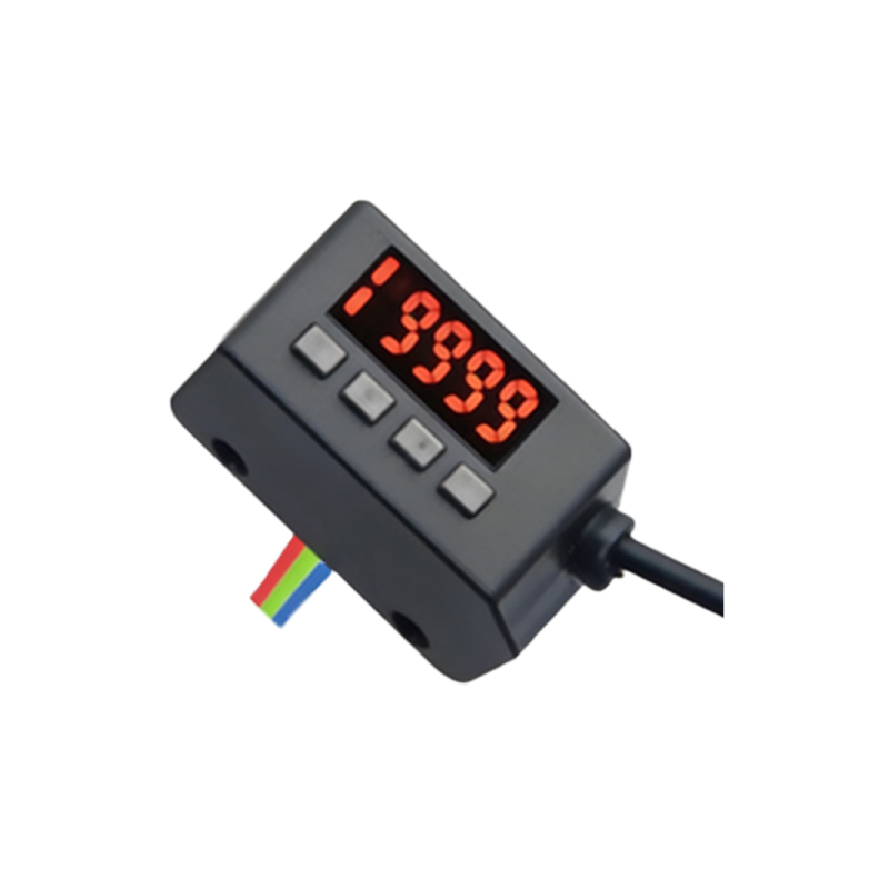
Key Design Parameters for Electrical Engineers
When designing a photoelectric sound pressure sensor, engineers must consider several parameters:
- Light Source Stability: A constant-intensity laser or temperature-compensated LED ensures minimal drift.
- Diaphragm Material and Thickness: Materials like Mylar or aluminum foil with thicknesses from 2 to 10 micrometers offer optimal frequency response up to 20 kHz.
- Detector Responsivity: High-speed photodiodes with responsivity above 0.5 A/W are preferred for capturing rapid acoustic fluctuations.
- Signal Conditioning: A transimpedance amplifier with low noise (< 1 pA/√Hz) and adjustable gain is essential for linear output in the range of 20 dB to 140 dB SPL.
- Shielding and Isolation: Optical and electrical shielding reduces ambient light interference and EMI, improving signal-to-noise ratio.
Circuit Implementation and Calibration
A typical circuit includes a constant current driver for the light source, a photodiode with a reverse bias voltage for fast response, and a two-stage amplifier. The first stage converts current to voltage, while the second stage provides bandpass filtering (e.g., 20 Hz to 20 kHz for audio applications). Calibration involves using a reference microphone to map output voltage to known sound pressure levels. A calibration curve, often linear within ±1 dB across the operating range, is stored in a microcontroller's EEPROM for real-time correction. Engineers should also account for temperature effects, as photodetector dark current increases with heat.
Advantages and Limitations in Industrial Settings
Photoelectric sensors excel in harsh environments due to their immunity to magnetic fields and ability to withstand corrosive gases. They also enable remote sensing through fiber optics, ideal for monitoring sound in hazardous areas. However, limitations include sensitivity to dust and vibrations, which require frequent cleaning or sealed enclosures. The optical alignment is critical; misalignment of even 0.1 degrees can cause signal loss. For high-precision applications, using a differential photodetector configuration can compensate for common-mode noise.
Practical Application Example: Real-Time Noise Monitoring
Consider a factory floor with rotating machinery generating noise up to 110 dB SPL. A photoelectric sensor module is mounted 1 meter from the source, with a 5 mW laser and a 50 µm thick aluminum diaphragm. The output signal is fed into a PLC via a 4-20 mA loop, with a response time of 1 ms. Data is logged and analyzed for OSHA compliance. Compared to a condenser microphone, the photoelectric system shows a 30% reduction in maintenance costs over six months, as it requires no recalibration for drift.
Conclusion and Future Directions
Photoelectric sensors represent a viable, robust alternative for sound pressure measurement in electrical engineering applications. Advances in MEMS-based diaphragms and integrated photonic circuits promise even smaller form factors and wider bandwidths up to 100 kHz. Engineers should explore hybrid systems combining photoelectric and capacitive elements to leverage the strengths of both technologies. As Industry 4.0 evolves, these sensors will play a key role in smart acoustic monitoring networks.