The Phenomenon of Dual Illumination
In industrial automation, photoelectric sensors are critical for object detection, often using LED indicators to signal operational status. A common issue engineers encounter is when both red and green lights on a sensor illuminate at the same time. This condition, known as "dual illumination," can confuse operators and indicate underlying faults. The red light typically signifies an output-off or alarm state, while green indicates output-on or normal operation. When both appear together, it points to a system anomaly that requires immediate diagnostic attention.
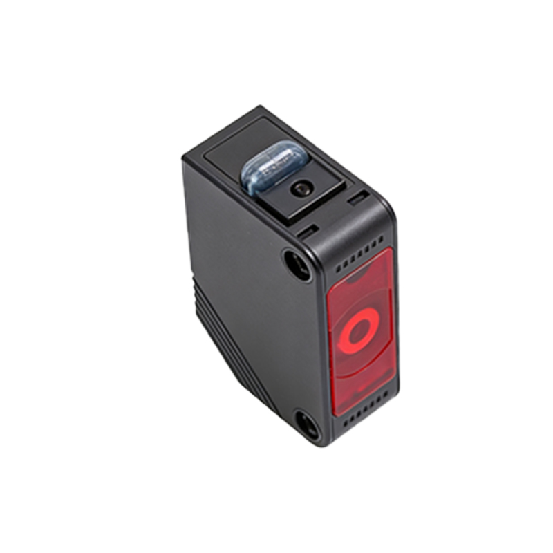
Root Causes: Electrical Interference
One primary cause is electrical interference from nearby high-power equipment, such as motors or variable frequency drives. This interference can induce false signals in the sensor’s output circuit, causing both LED indicators to trigger simultaneously. For example, in a packaging line, a photoelectric sensor near a conveyor motor may show mixed lights due to electromagnetic noise. Engineers should check shielding, grounding, and cable routing to mitigate this issue.
Root Causes: Wiring and Connection Errors
Incorrect wiring is another frequent culprit. If the sensor’s output is connected to a load with improper polarity or if the signal wire is shorted to the power line, the sensor may misinterpret the state. For instance, a miswired NPN sensor in a PLC system can cause both LEDs to remain lit. Verifying the sensor’s datasheet and using a multimeter to test connections can resolve this.
Root Causes: Sensor Malfunction
Internal component failure, such as a damaged output transistor or a faulty LED driver, can also produce dual illumination. Environmental factors like moisture or dust ingress may corrode internal circuits. Consider a case in a wet manufacturing environment where a sensor’s protective seal failed, leading to simultaneous red and green lights after a few months of operation. Regular inspection and replacement of aging sensors are recommended.
Root Causes: Configuration and Logic Conflicts
Some sensors allow adjustable output logic, such as light-on or dark-on modes. If the configuration is accidentally changed or conflicts with the control system’s expectations, dual lights may appear. For example, a sensor set to light-on but connected to a dark-on controller can cause both indicators to glow. Resetting the sensor to factory defaults and reprogramming it according to system requirements can fix this.
Diagnostic Steps for Engineers
To diagnose the problem, start by isolating the sensor from the load and testing it with a known good power supply. If both lights still appear, the sensor is likely defective. Next, examine wiring for shorts or opens using a continuity tester. Then, check for electrical noise by observing the sensor’s behavior when nearby machinery is turned off. Finally, verify the sensor’s configuration settings against the manufacturer’s guidelines.
Preventive Measures and Best Practices
To prevent dual illumination, use shielded cables for long runs, install ferrite beads on power lines, and follow proper grounding techniques. Additionally, select sensors with IP67 or higher ratings for harsh environments. Regular preventive maintenance, including cleaning and testing, can extend sensor life and reduce false indications. Documenting all sensor configurations and wiring diagrams also aids in quick troubleshooting.