What Is the Green Wire in an Optical Sensor?
The green wire in an optical sensor typically serves as the output signal line, commonly used in industrial automation for transmitting sensor status (e.g., object detection or absence). In standard wiring conventions, the green wire often corresponds to the normally open (NO) or normally closed (NC) output, depending on the sensor model and manufacturer. For example, in many three-wire DC sensors, the brown wire is for power (+V), blue for ground (0V), and green for the output signal. Understanding this color code is critical for correct installation in PLCs, relays, or controllers, preventing miswiring that could lead to equipment damage or false readings.
Common Wiring Configurations for the Green Wire
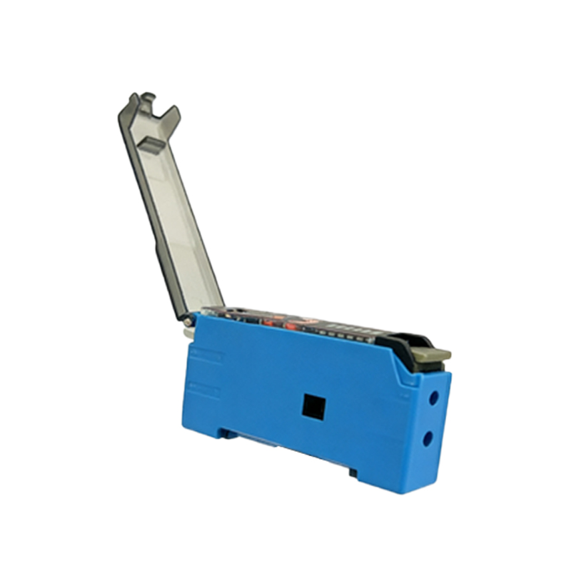
In typical 3-wire DC optical sensors, the green wire is connected to the load (e.g., a PLC input module or relay coil). For NPN (sinking) output sensors, the green wire delivers a low signal (0V) when activated, while PNP (sourcing) sensors output a high signal (+V). Always verify the sensor datasheet: some manufacturers use green for NPN output and black for PNP, but variations exist. For AC sensors, the green wire may be used for the switch output in a two-wire configuration. Use a multimeter to confirm voltage levels before permanent connection to avoid short circuits.
Troubleshooting Green Wire Issues
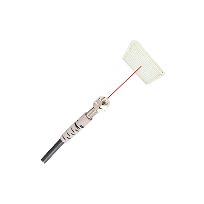
Common problems include signal dropout, false triggering, or no output. First, check the green wire connection for loose terminals or corrosion, especially in harsh environments. Measure voltage between green and blue wires: for PNP sensors, expect +V when active; for NPN, expect near 0V. If the sensor fails to respond, verify the sensor’s alignment with the target and clean the lens. Also, ensure the power supply (brown + blue) is within spec. A faulty green wire often indicates internal sensor damage—replace the unit if the output remains erratic after reconnection.
Safety and Standards for Green Wire Use
Adhere to IEC 61131-2 and local electrical codes when wiring optical sensors. The green wire should never be confused with ground or safety earth (which is usually green/yellow). Use proper strain relief and shielding to prevent electromagnetic interference. In high-vibration settings, apply ferrules to the green wire termination. Always power down the system before handling the green wire to avoid electrical shock.
Advanced Applications: Green Wire in Smart Sensors
Modern optical sensors with IO-Link or analog outputs may assign the green wire for data communication or 4-20mA current loops. For example, in photoelectric sensors with configurable outputs, the green wire could be programmed for timing functions or diagnostic signals. Refer to the sensor’s configuration software to map the green wire to the desired function. Always test the output in a non-critical system first to ensure compatibility.