Understanding Photoelectric Sensor Current Ratings
Photoelectric sensors are critical components in industrial automation, with their maximum current rating defining the load they can reliably drive. This parameter, typically specified in milliamperes (mA) or amperes (A), indicates the highest continuous current the sensor’s output can handle without thermal damage or performance degradation. For example, common photoelectric sensors offer ratings from 100 mA for standard DC outputs to 500 mA or more for high-power models. Engineers must select sensors with a current margin of at least 20% above the actual load to ensure long-term stability, especially in environments with voltage fluctuations or inductive loads.
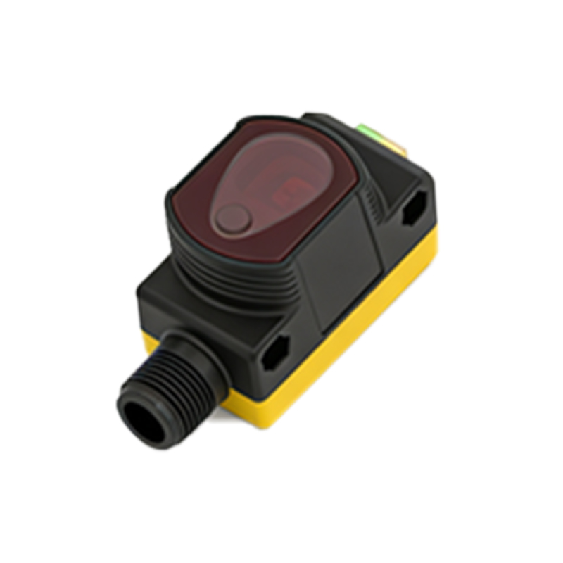
Factors Influencing Maximum Current Performance
The maximum current capacity depends on several design factors, including the output transistor type (NPN, PNP, or push-pull), operating voltage, and ambient temperature. For instance, NPN sinking outputs typically handle lower currents than PNP sourcing types due to internal resistance differences. Higher ambient temperatures reduce current capability, as semiconductor junctions degrade faster. Additionally, cable length and gauge impact voltage drop, potentially reducing the effective current available at the load. In practice, a 24 VDC sensor with a 200 mA rating may deliver only 180 mA at 60°C, requiring derating curves from manufacturers.
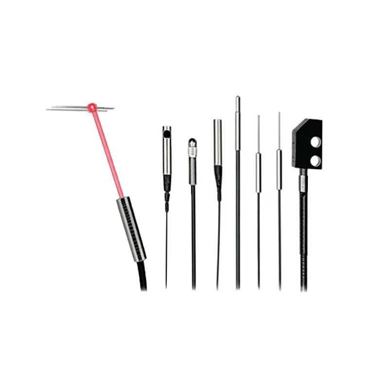
Common Pitfalls in Current Selection
Oversizing or undersizing the current rating can lead to system failures. Undersizing may cause premature sensor failure from overheating, while oversizing increases costs and circuit complexity. For example, using a 500 mA sensor for a 50 mA load might seem safe, but it often results in slower switching speeds due to higher internal capacitance. Another mistake is ignoring inrush current from capacitive loads, which can momentarily exceed the sensor’s maximum rating. Always consult datasheets for peak current limits and add a series resistor or snubber circuit for protection.
Best Practices for Current Optimization
To maximize performance, follow these guidelines: 1) Select sensors with a current rating at least 1.5 times the continuous load. 2) Use shielded cables with proper grounding to reduce noise interference that can trigger false readings. 3) Implement current-limiting resistors for LED indicators or small relays driven directly by the sensor. 4) For high-current loads like contactors, use an external relay or solid-state switch to isolate the sensor. Regular thermal imaging during commissioning can identify hotspots, ensuring the sensor operates within safe current limits.
Future Trends in Photoelectric Sensor Current Design
Emerging technologies like gallium nitride (GaN) transistors and advanced packaging are pushing current ratings beyond 1 A in compact form factors. These innovations reduce heat generation while improving switching speeds, enabling direct control of larger industrial valves or motors. Manufacturers are also integrating smart current monitoring with IoT interfaces, allowing real-time adjustment of output current based on load changes. For engineers, staying updated with these trends is key to designing robust, energy-efficient systems that meet evolving industry demands.