In the field of precision balancing, photoelectric sensors serve as critical components for synchronizing rotor position with vibration measurements. These sensors detect a reference mark on the rotor, typically a reflective strip or a notch, to trigger data acquisition at a specific angular position. For engineers, knowing the exact placement of these sensors is essential for achieving accurate unbalance correction, especially in high-speed or dynamic balancing applications.
In the field of precision balancing, photoelectric sensors serve as critical components for synchronizing rotor position with vibration measurements. These sensors detect a reference mark on the rotor, typically a reflective strip or a notch, to trigger data acquisition at a specific angular position. For engineers, knowing the exact placement of these sensors is essential for achieving accurate unbalance correction, especially in high-speed or dynamic balancing applications.
Common Mounting Positions: Radial vs. Axial Placement
The most standard location for a photoelectric sensor is radial to the rotor axis, aligned with the reference mark on the rotor circumference. This setup is widely used in horizontal balancing machines for fan impellers, motor armatures, and shafts. However, in situations where radial access is limited, such as in vertical balancing machines or when the rotor has a complex geometry, the sensor may be mounted axially, facing the end face of the rotor. Axial placement requires precise alignment with a reflective target on the rotor face, and it is often employed in disc-like rotors, such as brake rotors or flywheels.
Distance and Angle Considerations for Optimal Signal
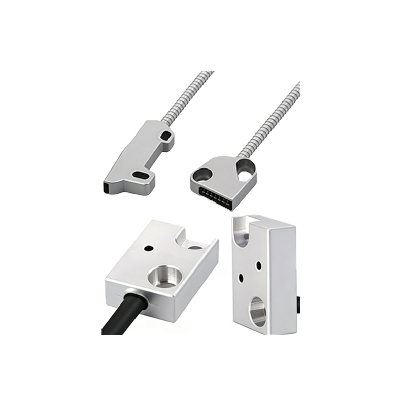
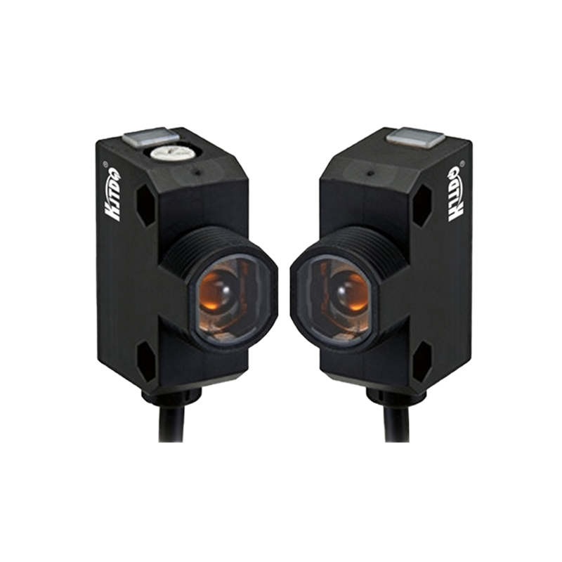
The sensor should be positioned at a distance of 5 to 15 mm from the rotor surface, depending on the sensor model and the reflectivity of the reference mark. For reflective-type photoelectric sensors, the angle of incidence relative to the rotor surface should be between 10° and 30° to avoid specular reflection errors. Engineers must also consider the rotor's vibration amplitude; if the sensor is too close, mechanical vibrations may cause false triggers, while excessive distance can lead to signal loss. A common practice is to use a fixed bracket or an adjustable mount to fine-tune the sensor position during calibration.
Environmental Factors and Sensor Protection
In industrial balancing machine environments, photoelectric sensors are often exposed to dust, oil mist, and temperature variations. Therefore, the sensor should be housed in a protective enclosure with an IP67 rating at minimum. For high-temperature applications, such as balancing turbine rotors, a heat-resistant sensor with a cooling jacket may be required. Additionally, the sensor cable should be routed away from high-current power cables to avoid electromagnetic interference (EMI). The mounting location should also allow easy access for cleaning and alignment, as accumulated dirt can degrade the sensor's performance.
Integration with Balancing Machine Control Systems
The sensor's output signal is typically fed into the balancing machine's measurement controller, which uses it as a zero-phase reference for polar coordinate calculation. Modern digital balancing systems often allow engineers to adjust the sensor's trigger angle and sensitivity via software. For best results, the sensor should be mounted rigidly to the machine frame, not to the rotor support structure, to avoid relative motion between the sensor and the rotor. This ensures that the angular reference remains stable even when the machine vibrates during operation.
Troubleshooting Common Sensor Location Issues
If the balancing machine shows inconsistent phase readings, the first step is to check the sensor's alignment with the reference mark. Misalignment of more than 2° can cause significant errors. Another common issue is the sensor detecting multiple reflections from adjacent surfaces; this can be resolved by using a polarized photoelectric sensor or by applying a black matte background around the reference mark. Engineers should also verify that the sensor's operating frequency range matches the rotor's rotational speed; for rotors running above 10,000 RPM, a fast-response sensor with a response time of less than 50 microseconds is necessary.
The most standard location for a photoelectric sensor is radial to the rotor axis, aligned with the reference mark on the rotor circumference. This setup is widely used in horizontal balancing machines for fan impellers, motor armatures, and shafts. However, in situations where radial access is limited, such as in vertical balancing machines or when the rotor has a complex geometry, the sensor may be mounted axially, facing the end face of the rotor. Axial placement requires precise alignment with a reflective target on the rotor face, and it is often employed in disc-like rotors, such as brake rotors or flywheels.
The sensor should be positioned at a distance of 5 to 15 mm from the rotor surface, depending on the sensor model and the reflectivity of the reference mark. For reflective-type photoelectric sensors, the angle of incidence relative to the rotor surface should be between 10° and 30° to avoid specular reflection errors. Engineers must also consider the rotor's vibration amplitude; if the sensor is too close, mechanical vibrations may cause false triggers, while excessive distance can lead to signal loss. A common practice is to use a fixed bracket or an adjustable mount to fine-tune the sensor position during calibration.
In industrial balancing machine environments, photoelectric sensors are often exposed to dust, oil mist, and temperature variations. Therefore, the sensor should be housed in a protective enclosure with an IP67 rating at minimum. For high-temperature applications, such as balancing turbine rotors, a heat-resistant sensor with a cooling jacket may be required. Additionally, the sensor cable should be routed away from high-current power cables to avoid electromagnetic interference (EMI). The mounting location should also allow easy access for cleaning and alignment, as accumulated dirt can degrade the sensor's performance.
The sensor's output signal is typically fed into the balancing machine's measurement controller, which uses it as a zero-phase reference for polar coordinate calculation. Modern digital balancing systems often allow engineers to adjust the sensor's trigger angle and sensitivity via software. For best results, the sensor should be mounted rigidly to the machine frame, not to the rotor support structure, to avoid relative motion between the sensor and the rotor. This ensures that the angular reference remains stable even when the machine vibrates during operation.
If the balancing machine shows inconsistent phase readings, the first step is to check the sensor's alignment with the reference mark. Misalignment of more than 2° can cause significant errors. Another common issue is the sensor detecting multiple reflections from adjacent surfaces; this can be resolved by using a polarized photoelectric sensor or by applying a black matte background around the reference mark. Engineers should also verify that the sensor's operating frequency range matches the rotor's rotational speed; for rotors running above 10,000 RPM, a fast-response sensor with a response time of less than 50 microseconds is necessary.