Introduction to Photoelectric Sensor Polarity
Photoelectric sensors are essential components in industrial automation, used to detect objects without physical contact. A common question among engineers and technicians is whether photoelectric sensors have positive and negative terminals. The answer is yes, but it depends on the sensor type, output configuration, and wiring requirements. Understanding polarity is crucial for proper installation, preventing damage, and ensuring reliable operation in applications like conveyor systems, packaging machinery, and robotic assembly lines.
Why Polarity Matters in Photoelectric Sensors
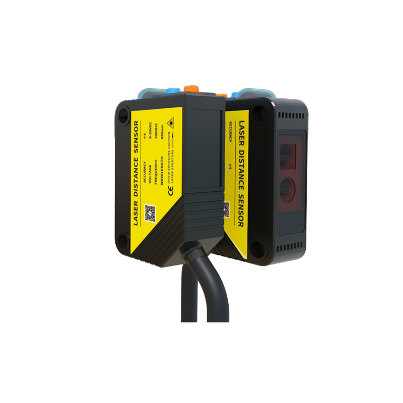
Polarity refers to the correct orientation of electrical connections, typically involving a positive (V+) and negative (V-) or ground terminal. In photoelectric sensors, polarity is critical for power supply and signal output. Most sensors operate on DC voltage (e.g., 10-30 VDC) and require correct polarity to function. Reversing polarity can damage internal electronics, such as transistors or photodiodes, leading to sensor failure. Additionally, output types like NPN (sinking) and PNP (sourcing) define polarity in signal lines, affecting how the sensor interfaces with controllers like PLCs.
Types of Photoelectric Sensors and Their Polarity
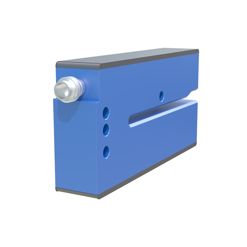
There are three main types: through-beam, retro-reflective, and diffuse sensors. All typically have a power supply with polarity (V+ and V-). For example, a common M18 threaded photoelectric sensor might have a 4-wire configuration: brown (V+), blue (V-), black (NPN output), and white (PNP output). Polarity must be observed on the brown and blue wires to avoid short circuits. Some sensors also include polarity protection diodes, but relying on them is risky. Always check the datasheet for wiring diagrams.
NPN vs. PNP Outputs and Polarity
NPN outputs sink current to ground (negative), so the load is connected between the output and V+. PNP outputs source current from V+, so the load is between the output and V-. This creates a polarity distinction: for NPN, the sensor's output terminal is active low (negative), while for PNP, it is active high (positive). Misconnecting these can cause no detection or erratic behavior. For instance, a PNP sensor wired to an NPN PLC input will not trigger correctly without a pull-up resistor.
Common Polarity Mistakes and Troubleshooting
A frequent error is reversing power wires, especially in retrofit installations. Symptoms include no LED indicator, overheating, or immediate failure. Another mistake is mixing NPN and PNP outputs with incompatible loads. Use a multimeter to verify voltage between V+ and V- (should match rated voltage, e.g., 24 VDC). Check output polarity by measuring between output and ground. If the sensor is unresponsive, first test power polarity, then output configuration. Always use color-coded wiring standards (e.g., IEC 60947-5-2) to avoid errors.
Best Practices for Wiring Photoelectric Sensors
To ensure correct polarity, follow these steps: 1) Confirm sensor specifications (voltage range, output type) from the datasheet. 2) Use a regulated power supply with proper grounding. 3) Connect brown wire to V+ and blue wire to V- for DC sensors. 4) For AC sensors (rare, but exist), polarity may not matter, but confirm. 5) Use shielded cables in noisy environments to prevent interference. 6) Test with a dummy load before final installation. These practices extend sensor life and improve system reliability.
Conclusion: Ensuring Polarity Accuracy
In summary, photoelectric sensors do have polarity, primarily in power and output connections. Engineers must carefully adhere to wiring diagrams, understand NPN/PNP logic, and verify with test equipment. By mastering polarity, you reduce downtime, avoid costly replacements, and enhance automation performance. Always consult manufacturer documentation for specific sensor models, as polarity requirements can vary.