Understanding the Basics of Photoelectric Sensors
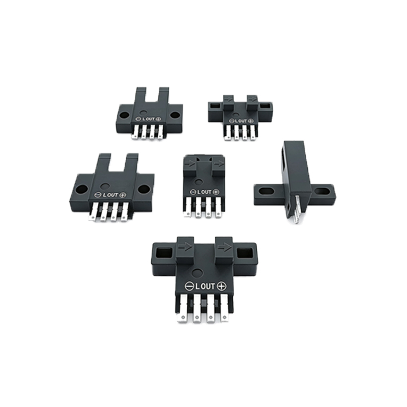
As a professional in the electrical and automation industry, you often encounter slot-type photoelectric sensors with different wiring configurations. A standard 4-wire sensor typically includes two power wires (brown for +V and blue for 0V) and two output wires (black for NPN and white for PNP, or vice versa depending on the model). However, when your control system only supports a 3-wire setup—like a PLC with a single digital input and common ground—you need to adapt the wiring. This guide explains how to safely and effectively convert a 4-wire sensor to a 3-wire connection, ensuring reliable operation.
Identifying the 4-Wire Sensor Pinout
Before making any connections, consult the sensor datasheet. Typically, the color codes are: brown (power supply +, 10-30V DC), blue (power supply -, 0V), black (output 1, often NPN or PNP), and white (output 2, complementary). For example, in a through-beam slot sensor, the black wire might be the NPN normally-open output, while the white is the PNP normally-open. Use a multimeter to verify the voltage between brown and blue when powered—this confirms correct polarity. Never assume colors without verification, as manufacturers may vary.
Selecting the Appropriate Output for 3-Wire Use
In a 3-wire system, you typically have three connections: power (+V), ground (0V), and signal output. For a 4-wire sensor, you must choose only one output wire (either black or white) to connect as the signal. If your PLC input is sinking (NPN), select the black wire if it is NPN output; if sourcing (PNP), select the white wire if it is PNP output. Most industrial controllers prefer PNP for positive logic, but check your system specs. The unused output wire should be insulated and capped to prevent short circuits.
Wiring Steps for NPN Configuration
For a 3-wire NPN system (common for Japanese PLCs), connect the sensor as follows: Brown wire to +V (24V DC), Blue wire to 0V (ground), and Black wire to the PLC input (sinking). The White wire remains unconnected—wrap it with electrical tape or use a wire nut. Ensure the power supply is off during wiring. After powering on, test the sensor by interrupting the slot: the input should go low (0V) when the target is present, and high (24V) when clear. If the logic is reversed, swap the black wire with the white wire (if white is NPN output).
Wiring Steps for PNP Configuration
In a PNP 3-wire system (common for European PLCs), connect: Brown to +V, Blue to 0V, and White wire to the PLC input (sourcing). The Black wire is left unused and insulated. PNP outputs provide a positive voltage (24V) when active, so expect the input to go high when the slot is blocked. Verify with a multimeter: measure voltage between white and blue—it should be 24V when triggered, and near 0V when not. If the behavior is opposite, you may need to swap to the black wire if it is PNP output, but double-check the datasheet.
Troubleshooting Common Issues
If the sensor does not work after conversion, first check power: ensure brown is at +V and blue at 0V with at least 10V difference. Next, confirm that the unused wire is not shorting to ground or power—use a continuity test. If the signal is always on or off, verify the output type matches your PLC input. For example, an NPN sensor connected to a PNP input will not trigger correctly—you may need a pull-up resistor (e.g., 1kΩ to +V) on the signal line. Lastly, ensure the sensor’s load current does not exceed the PLC input rating (typically 5-10 mA). If all else fails, consult the sensor manual for specific wiring diagrams.