2026-04-24
Tech Hub
By 创始人
Understanding Photoelectric Sensor Speed Measurement: A Comprehensive Guide for Electrical Engineers
Introduction to Photoelectric Sensors for Speed Measurement
Photoelectric sensors are non-contact devices that use light beams to detect objects or changes in light intensity, making them ideal for speed measurement in industrial applications. Unlike mechanical or magnetic sensors, they eliminate wear and tear, offering high accuracy and fast response times. In electrical engineering, these sensors convert rotational speed into electrical signals, which can be analyzed for process control, motor monitoring, or conveyor belt synchronization. Their working principle involves emitting a light beam (visible or infrared) toward a reflective target or through a slotted disk, and detecting interruptions or reflections to generate pulse signals.
Principle of Operation: How Speed is Measured
Speed measurement with a photoelectric sensor relies on the relationship between rotational motion and pulse frequency. A typical setup includes a rotating shaft with a marked pattern (e.g., black-and-white stripes) or a slotted disk. As the shaft rotates, the sensor emits a light beam that is alternately blocked and transmitted, creating a train of electrical pulses. The frequency of these pulses is directly proportional to the rotational speed, expressed in revolutions per minute (RPM). For example, a disk with 60 slots produces 60 pulses per revolution, allowing engineers to calculate RPM by monitoring the pulse frequency. Key parameters include sensor response time (often in microseconds) and the number of marks per revolution (NPR), which determine resolution.
Key Components and Selection Criteria
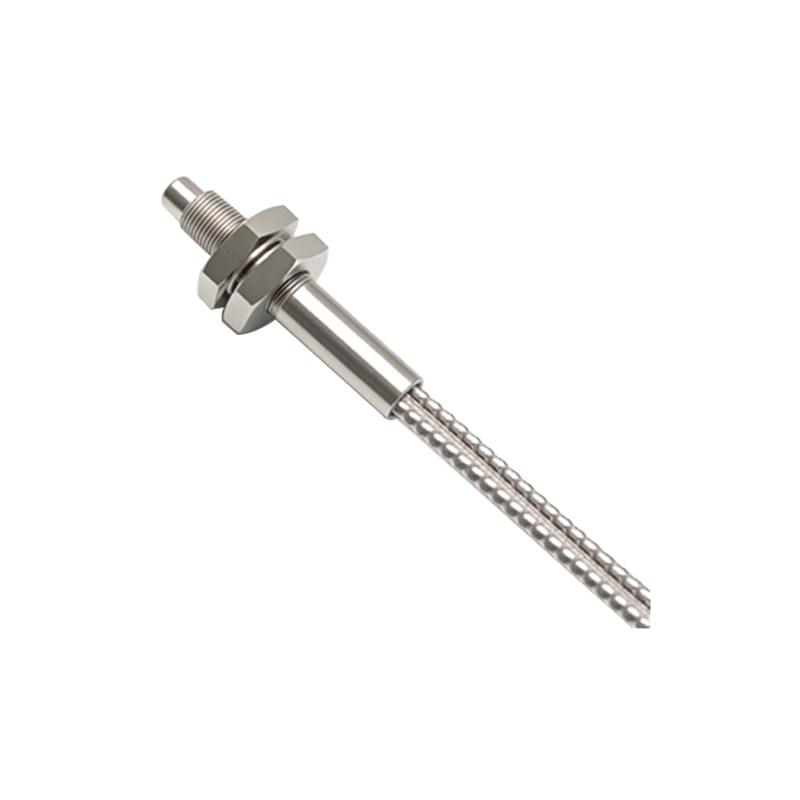
When designing a speed measurement system, engineers must consider sensor types: through-beam, retro-reflective, or diffused. For high-speed applications, through-beam sensors are preferred due to their longer sensing range and immunity to ambient light. Retro-reflective sensors simplify mounting but require reflective targets. Selection criteria include response frequency (up to several kHz), sensing distance (e.g., 0.1–10 meters), and environmental factors like dust or vibration. For instance, a sensor with a response time of 0.5 ms can track speeds up to 120,000 RPM if 60 pulses per revolution are used. Engineers should also evaluate output types (NPN, PNP, or analog) to interface with PLCs or microcontrollers.
Advantages and Limitations in Industrial Contexts
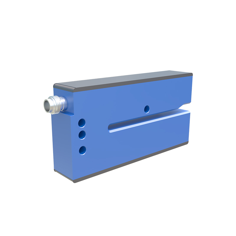
Photoelectric sensors offer distinct advantages: non-contact operation reduces mechanical failure, high immunity to electromagnetic interference, and ability to measure both rotational and linear speeds. They are widely used in packaging, automotive assembly, and robotics. However, limitations include sensitivity to contamination (oil, fog, or dirt) and ambient light, which may cause false triggers. For precise measurement, engineers often use shielded cables and regulators to stabilize output signals. In high-vibration environments, fiber-optic photoelectric sensors provide better reliability by separating the electronics from the sensing head.
Practical Implementation and Signal Processing
To implement speed measurement, engineers connect the sensor output to a frequency counter or pulse timer. A common approach uses a microcontroller to count pulses over a fixed time window (e.g., 1 second) and convert to RPM using the formula: RPM = (Pulse Count × 60) / (Slots per Revolution). For dynamic systems, real-time processing with digital filters (e.g., moving average) smooths fluctuations. Engineers should also calibrate the system by measuring a known reference speed and adjusting threshold levels. For harsh environments, considering IP67 or higher ratings ensures longevity.
Conclusion: Future Trends and Engineering Best Practices
Photoelectric sensor technology continues to evolve, with newer models offering integrated microcontrollers for self-diagnosis and wireless data transmission. Engineers should prioritize sensor selection based on application needs, including speed range, environmental conditions, and accuracy requirements. Regular maintenance, such as cleaning lenses and verifying alignment, prevents signal degradation. By mastering these principles, electrical engineers can optimize automation processes, reduce downtime, and enhance system reliability.