Introduction to Photoelectric Sensing for Speed Measurement
In the realm of industrial automation and motion control, precise speed measurement of rotating machinery is paramount. Among the various techniques available, photoelectric sensor-based tachometry stands out for its non-contact nature, high accuracy, and reliability. This method utilizes light beams to detect rotational or linear motion, converting it into a measurable electrical signal. Unlike mechanical tachometers that require physical contact, photoelectric sensors eliminate friction, wear, and potential load effects on the system being measured. This makes them ideal for applications ranging from high-speed spindles in manufacturing to delicate laboratory equipment. The core principle involves interrupting or reflecting a light source, with the sensor detecting these changes to calculate rotational speed or velocity.
Fundamental Operating Principles
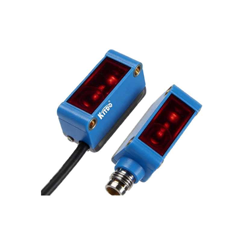
The operation of a photoelectric sensor for motor speed measurement typically relies on one of two primary configurations: the through-beam (or opposed) mode and the reflective (or proximity) mode. In the through-beam setup, an emitter and a receiver are positioned opposite each other. A disc with slots or markings, attached to the motor shaft, rotates between them. Each time a slot passes, light reaches the receiver, generating a pulse. The reflective mode employs a single unit housing both the emitter and receiver. It detects light reflected from a pre-marked or specially designed reflective surface on the rotating component. The frequency of the generated pulse train is directly proportional to the rotational speed. This frequency (f) is processed by a controller or frequency-to-voltage converter to yield the speed value in revolutions per minute (RPM) using the formula: RPM = (f * 60) / N, where N is the number of pulses per revolution.
Key Components and Sensor Types
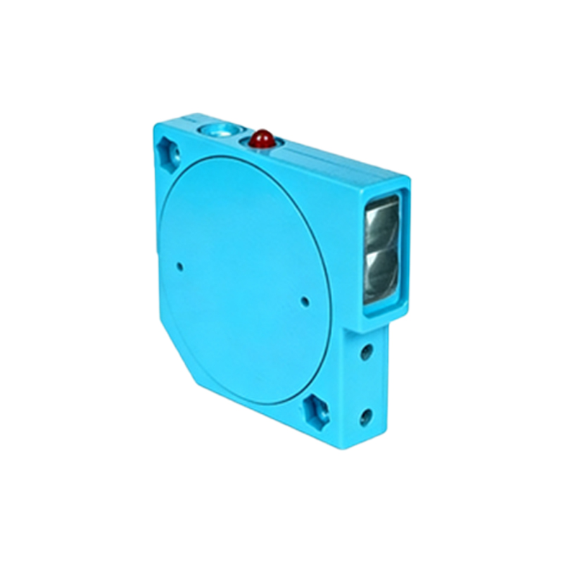
A complete photoelectric tachometry system comprises several critical components. The light source, traditionally an LED or laser diode, provides a consistent beam. The photodetector, often a phototransistor or photodiode, converts the received light intensity into an electrical current. The optical components, such as lenses and filters, shape the beam and reject ambient light interference. The pulse-processing circuitry conditions the signal. Common sensor types include diffuse reflective sensors, which detect light bounced off a target; retro-reflective sensors, which use a reflector; and the aforementioned through-beam sensors. For motor applications, the choice depends on factors like required resolution, mounting constraints, and environmental conditions such as dust or oil mist.
System Design and Installation Considerations
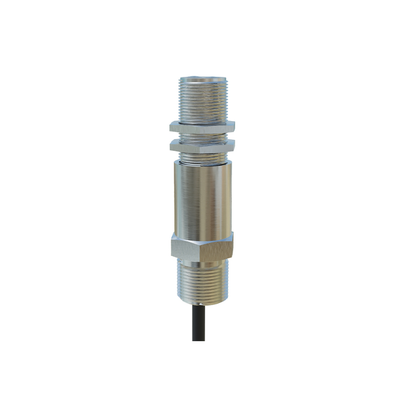
Successful implementation requires careful design. The number of pulses per revolution (N) on the encoder disc or marked surface determines the resolution; more slots provide higher resolution but demand a faster sensor response. The sensor must be selected with a sufficient response frequency to handle the maximum expected pulse rate. Alignment is critical, especially for through-beam sensors, to ensure reliable signal detection. Environmental challenges like vibration, temperature extremes, and contamination by dirt or coolant must be addressed through proper sensor housing selection (often with an IP67 or higher rating) and regular maintenance. Electrical noise in industrial settings can interfere with the signal, necessitating shielded cables and proper grounding practices.
Signal Processing and Data Interpretation
The raw pulse signal from the photoelectric sensor requires conditioning. This typically involves amplification, noise filtering (using low-pass or band-pass filters), and conversion into a clean digital square wave via a Schmitt trigger circuit. Modern digital controllers, PLCs (Programmable Logic Controllers), or dedicated tachometer modules then measure the frequency or period of this wave. For variable speed drives, instantaneous speed feedback is crucial for closed-loop control. Advanced systems may also perform diagnostics, detecting anomalies like missing pulses that could indicate sensor misalignment, disc damage, or sudden load changes. The processed speed data can be displayed locally, transmitted to a SCADA system, or used directly in a control algorithm.
Advantages Over Alternative Speed Measurement Methods
Photoelectric sensors offer distinct benefits compared to other technologies like magnetic encoders, Hall-effect sensors, or mechanical tachogenerators. Their primary advantage is the complete absence of physical contact, leading to zero mechanical wear and no added load torque. They provide extremely high resolution and accuracy, capable of measuring very high speeds. They are generally immune to magnetic fields, making them suitable for use near large motors or transformers. Furthermore, they can detect non-metallic objects and are versatile in their mounting configurations. While magnetic encoders are robust in dirty environments, photoelectric sensors excel in clean or moderately challenging conditions where high precision is needed.
Common Industrial Applications
The applications are vast across industries. In automotive manufacturing, they monitor the speed of conveyor belts, assembly robots, and engine testing dynamometers. In the packaging industry, they ensure precise speed synchronization of multiple drives on filling and labeling machines. CNC machine tools rely on them for spindle speed feedback. They are integral to wind turbine pitch control systems, paper mill rollers, and textile machinery. In scientific research, they measure the rotational velocity of centrifuges and experimental apparatus. Any application requiring reliable, non-contact speed feedback for control, monitoring, or safety purposes is a potential candidate for photoelectric tachometry.
Troubleshooting and Maintenance Best Practices
Even robust systems can encounter issues. Common problems include loss of signal, erratic readings, or complete failure. Troubleshooting should start with a visual inspection for misalignment, dirt accumulation on lenses or reflectors, and physical damage to the encoder disc. Checking the light source output and receiver sensitivity with a manufacturer-recommended procedure is essential. Electrical checks involve verifying supply voltage, output signal levels, and cable integrity. Regular preventive maintenance includes cleaning optical surfaces with appropriate materials, checking mounting stability, and verifying calibration against a known reference. Keeping a log of performance data can help in predicting sensor lifespan and planning replacements proactively.
Future Trends and Technological Advancements
The future of photoelectric motor speed measurement is intertwined with advancements in optoelectronics and digital integration. Miniaturization of components allows for smaller, more compact sensors suitable for tight spaces. The integration of IO-Link and other smart communication protocols enables sensors to transmit not just speed data, but also diagnostic information like lens contamination levels or internal temperature. Enhanced algorithms for signal processing can extract more information from the pulse train, potentially identifying vibration signatures or early signs of bearing wear. Furthermore, the development of more robust light sources and detectors continues to expand the operational envelope of these sensors into harsher environments, ensuring their continued relevance in Industry 4.0 and smart factory ecosystems.