Understanding the Basic Operation Principle
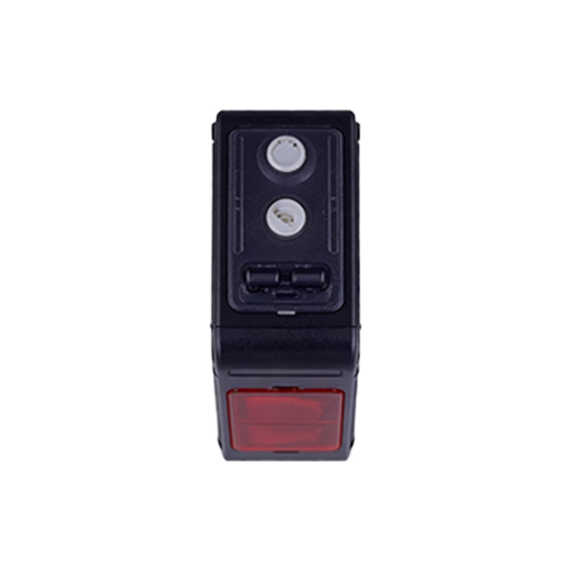
A reflective photoelectric sensor operates by emitting a beam of light, typically from an LED, towards a target. The sensor's receiver then detects the light reflected back from that target. The presence or absence of this reflected signal, and its intensity, is used to determine the target's presence, absence, distance, or color. When the sensor's indicator light, often an LED labeled "Output" or "Power," fails to illuminate, it signifies a fundamental failure in the system's operation. This lack of indication is a primary symptom that requires systematic investigation. The issue could stem from the power supply, the sensor's internal components, the optical path, the target itself, or the output load and wiring.
Initial Power Supply Verification
The first and most critical step is to verify the power supply. Ensure that the correct voltage (e.g., 10-30 VDC for many models) is being supplied to the sensor's designated power terminals. Use a reliable multimeter to measure the voltage directly at the sensor's terminals, not just at the source. Check for proper polarity; reversing the positive and negative connections is a common installation error that will prevent operation. Inspect the wiring for loose connections, corrosion, or breaks. Also, confirm that the power supply unit has adequate current capacity and is functioning correctly. A sensor will not activate without stable and correct power.
Inspecting Sensor Configuration and Settings
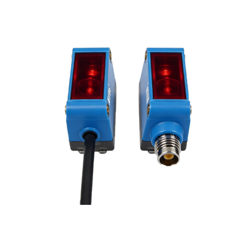
Many modern reflective sensors are configurable. A sensor set to the wrong operating mode (e.g., light-on vs. dark-on) might not behave as expected, though the power indicator might still be on. However, if the configuration involves internal switches or teaching functions that were incorrectly set, it could affect the sensor's startup logic. For self-contained units, ensure any sensitivity potentiometers or timing adjustments are set within a functional range. Refer to the manufacturer's datasheet for the correct default or required settings for your application. A factory reset, if possible, can rule out configuration errors.
Examining the Optical Path and Target Conditions
The core function of the sensor is optical. If the power is confirmed but there is no output indication, the problem may lie in the light path. First, ensure the sensor's lens is clean and free of obstructions like dust, oil, or debris. Even a thin film can drastically reduce performance. Next, evaluate the target. The sensor is designed for specific materials, colors, and distances. A highly absorbent (dark) or transparent target may not reflect sufficient light. The target might also be outside the sensor's effective sensing range or at an extreme angle. Test with a standard, high-reflectivity target (like white paper) at the recommended distance to isolate the target as the variable.
Diagnosing Internal Component Failure
If power, configuration, and optical path are confirmed correct, internal failure is likely. The emitting LED can degrade or burn out over time, especially if subjected to current surges or excessive duty cycles. The phototransistor or photodiode receiver can also fail. Environmental factors are a major culprit: excessive vibration can damage internal solder joints, extreme temperatures can degrade components, and moisture ingress can cause short circuits or corrosion. Contamination inside the housing, though sealed, can sometimes occur. Without specialized equipment, diagnosing specific internal component failure is challenging and often leads to sensor replacement.
Checking Output Circuit and Load Connections
The sensor's output stage must be correctly connected to its load (e.g., a PLC input, relay, or indicator). A faulty or incompatible load can cause issues. Verify the wiring of the output signal wire. For a sinking (NPN) output sensor, the load must be connected between the output terminal and the positive supply. For a sourcing (PNP) output, the load connects between the output and common negative. An incorrect connection can prevent the output transistor from switching properly. Additionally, check if the load is short-circuited or draws current exceeding the sensor's maximum switching capacity, which could cause the sensor to shut down its output as a protective measure.
Environmental Interference and Electrical Noise
Harsh industrial environments present unique challenges. Strong ambient light, such as direct sunlight or powerful strobes, can saturate the receiver, effectively blinding the sensor. Electrical noise from motors, welders, or variable frequency drives can induce false signals or disrupt the sensor's internal circuitry. Ensure the sensor is shielded or rated for such environments. Using shielded cables with proper grounding (drain wire grounded at the controller end only) is crucial. Power line fluctuations or spikes can also reset or damage the sensor. Installing a surge suppressor or line filter on the power supply input may be necessary for reliable operation in noisy plants.
Systematic Troubleshooting Procedure Summary
Follow a logical sequence to efficiently resolve the issue. Step 1: Visually inspect for physical damage, loose wires, and clean the lens. Step 2: Measure and confirm correct power supply at the sensor terminals. Step 3: Verify sensor configuration (mode, sensitivity) against the datasheet. Step 4: Test with a known-good, high-reflectivity target at the specified sensing distance. Step 5: Check output wiring and load compatibility and current draw. Step 6: Isolate the sensor from potential environmental interference. Step 7: If possible, substitute the sensor with a known-working unit of the same model to confirm the fault. This process will identify the fault domain in the vast majority of cases, guiding you toward repair or replacement.