Understanding the "No Light" Condition in Photoelectric Sensors
A "no light" condition in a photoelectric sensor is a critical fault state where the sensor's receiver does not detect the expected light beam from its emitter. This failure halts the detection process entirely, rendering the sensor inoperative for its intended purpose of presence sensing, counting, or positioning. It is distinct from a "no signal" or "beam blocked" condition, which is often a normal operational state. The "no light" fault indicates a fundamental breakdown in the sensor's core optical pathway. This condition can be triggered by several root causes, ranging from complete physical obstruction and severe misalignment to catastrophic failure of the emitter (LED or laser diode) or receiver (phototransistor or photodiode) components. In harsh industrial environments, contamination from oil, dust, or metal shavings can coat the lenses so thoroughly that light transmission is completely inhibited. Immediate troubleshooting is essential to restore system functionality and prevent costly production downtime.
Systematic Diagnostic Procedure for No Light Faults
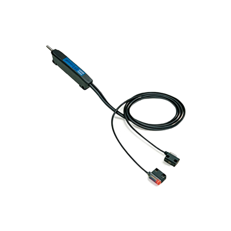
A structured, step-by-step approach is vital for efficient diagnosis. Begin with a thorough visual inspection of both the emitter and receiver lenses for any obvious physical damage, cracks, or heavy accumulation of dirt, grease, or paint. Verify that any protective caps installed during shipping have been removed. Next, check the power supply connections and voltage at the sensor terminals using a multimeter. Ensure the voltage is within the sensor's specified range (e.g., 10-30 VDC) and that polarity is correct. A simple but effective test is to temporarily swap the suspected faulty sensor with a known-good unit of the same model from a non-critical part of the line. If the problem follows the sensor, the fault is internal. If the problem remains at the original location, the issue lies in the mounting, alignment, or external environment.
Advanced Testing with an Optical Power Meter
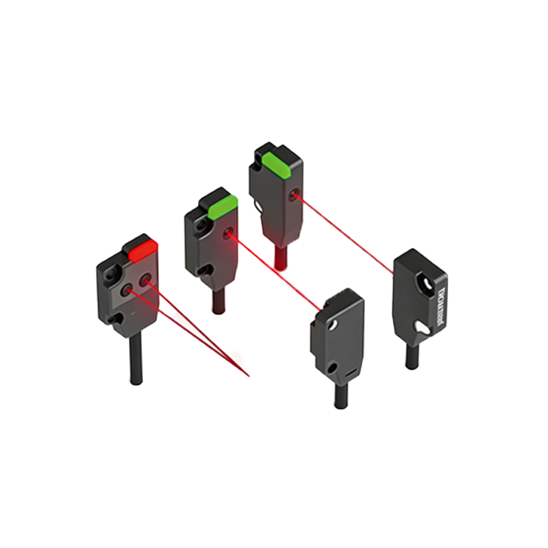
For conclusive evidence of emitter failure, an optical power meter is the professional tool of choice. Disconnect the sensor from its controller and carefully connect the emitter's output to the meter according to the sensor's datasheet specifications, often requiring a specific test mode or jumper setting. A reading of zero or significantly below the manufacturer's specified output confirms a dead emitter. Similarly, you can test the receiver by aiming a known-good light source (like another sensor's emitter or a calibrated test tool) at its lens while monitoring its output signal. The absence of a signal change indicates receiver failure. Always refer to the manufacturer's technical documentation for approved testing procedures and safe optical power levels to avoid damaging test equipment or your eyesight.
Environmental and Interference Factors
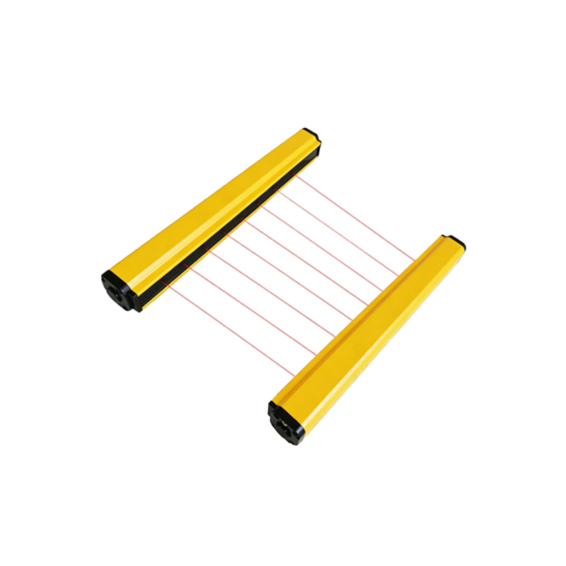
The operating environment is a frequent culprit. Intense ambient light from welding arcs, halogen lamps, or direct sunlight can saturate the receiver, creating a perceived "no light" condition because the sensor's modulated signal is drowned out. Ensure the sensor is rated for the environmental light immunity of your application. Cross-talk between closely mounted sensors operating at the same frequency can also cause interference. Changing the operating frequency (if the sensor supports it) or physically repositioning the sensors can resolve this. Additionally, consider the target properties; a perfectly clear or highly reflective target might not reflect sufficient light back to a retro-reflective or diffuse sensor, mimicking a no-light fault.
Corrective Actions and Preventive Maintenance
Once the root cause is identified, take appropriate corrective action. For dirty lenses, clean them with a soft, lint-free cloth and a suitable lens cleaner, never with abrasive materials. For misalignment, use precise alignment tools and follow the manufacturer's guidelines, often involving alignment LEDs or audible indicators. If the emitter or receiver is faulty, the sensor unit typically must be replaced, as these components are integral. For preventive maintenance, establish a regular schedule for lens inspection and cleaning. Use sensors with appropriate IP (Ingress Protection) ratings for the environment—such as IP67 or IP69K for washdown areas. Implement protective measures like physical guards to shield sensors from impact or buildup, and use sunshades or housings in areas with strong ambient light.
When to Consult Manufacturer Support
If the diagnostic steps do not resolve the issue, or if the failure is recurrent, contact the sensor manufacturer's technical support. Have the sensor model number, serial number, and detailed notes on the fault symptoms, environmental conditions, and tests performed ready. They can provide model-specific insights, advanced diagnostics, and information on known issues or firmware updates. In complex systems with networked sensors, the problem might lie in the configuration of the controller or PLC rather than the sensor itself, requiring a systems-level analysis that support engineers are best equipped to handle.