Defining Limit Error in Photoelectric Sensing
In the realm of industrial automation, the performance of photoelectric sensors is critically defined by their accuracy and reliability. A fundamental parameter governing this performance is the "Limit Error." This term refers to the maximum permissible deviation between the sensor's measured value and the true value of the target parameter under specified operating conditions. It is not a typical, repeatable error but represents the worst-case boundary of inaccuracy, encompassing all potential sources of deviation. Understanding this concept is paramount for system designers and engineers, as it directly impacts the robustness of automated processes, quality control thresholds, and overall system safety. The limit error provides a crucial safety margin, ensuring that even under non-ideal conditions—such as voltage fluctuations, temperature extremes, or target surface variations—the sensor's output remains within a band that the control system can interpret correctly without causing malfunctions or safety hazards.
Primary Sources Contributing to Total Error
The total limit error of a photoelectric sensor is an aggregate of several distinct error sources. First, inherent electronic noise within the sensor's amplifier and receiver circuitry creates a baseline of uncertainty. Second, the properties of the light source, typically an LED or laser diode, contribute significantly. Variations in emitted light intensity due to aging, temperature sensitivity (wavelength drift), and supply voltage ripple directly affect the received signal strength. Third, environmental factors are major contributors. Ambient light interference, especially from high-intensity sources like sunlight or welding arcs, can saturate the receiver. Temperature swings affect both electronic components and the mechanical housing, potentially causing minute shifts in optical alignment. Finally, target-related characteristics—such as color, reflectivity, surface finish (matte vs. glossy), size, and angle of incidence—can cause substantial variations in the reflected or interrupted light beam, leading to detection point shifts.
Quantitative Analysis and Specification Sheets
Manufacturers specify limit error in datasheets, though the terminology may vary (e.g., "accuracy," "repeatability," or "hysteresis"). For diffuse reflective sensors, the limit error is often expressed as a percentage of the sensing distance or as a fixed distance (e.g., ±2% of Sn or ±5 mm). For through-beam and retro-reflective types, the error is typically much smaller and may be related to the response time. A thorough quantitative analysis requires examining graphs for temperature drift, supply voltage influence, and repeatability. Engineers must carefully dissect these specifications: "repeatability" usually denotes the error under constant conditions, while "accuracy" or "total error" often aligns more closely with the limit error concept, considering multiple influencing variables. It is a critical mistake to consider only the nominal sensing distance without accounting for the associated error band, which defines the true effective operating range.
Impact on System Design and Guard Banding
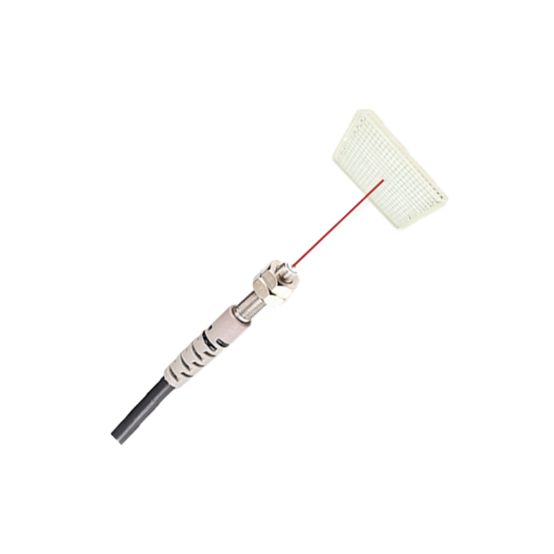
The practical implication of limit error is the necessity for "guard banding" in system design. If a sensor with a limit error of ±3 mm is used to detect an object on a conveyor for a cutting operation, the physical cut point must be programmed with a safety margin exceeding 3 mm from the sensor's trigger point. This ensures that even at the extreme edges of the error band, the cut is always accurate. Similarly, in positioning applications, the error budget from all sensors and actuators must be summed to guarantee system precision. Ignoring the limit error leads to intermittent failures, reduced product quality, and increased downtime. System designers must select sensors whose limit error is compatible with the application's tolerance requirements and then design mechanical layouts and logic controls that incorporate this error margin, effectively derating the sensor's nominal performance for guaranteed real-world operation.
Calibration and Compensation Strategies
While limit error defines the worst-case bounds, its effects can be mitigated through calibration and intelligent compensation. Initial teach-in or calibration procedures, where the sensor is programmed under actual operating conditions with representative targets, can null out systematic offsets. Advanced sensors with digital outputs and IO-Link communication allow for real-time monitoring of signal strength and parameter adjustment. Temperature compensation circuits within the sensor can reduce thermal drift. For highly critical applications, using a reference sensor or implementing software-based filtering and averaging algorithms can statistically reduce the influence of random error components, effectively narrowing the operational error band experienced in practice. However, it is crucial to remember that these strategies improve typical performance but do not alter the fundamental limit error specified by the manufacturer; they merely reduce the probability of operating at those extremes.
Selection Criteria for Minimizing Error Impact
Choosing the right sensor type is the first defense against excessive limit error. Through-beam sensors generally offer the highest accuracy and smallest error band due to their strong, direct signal. For reflective applications, background suppression (BGS) sensors are superior to standard diffuse sensors for maintaining consistent detection points regardless of target color or reflectivity, thereby reducing one major error source. Key selection parameters include: a stated limit error or accuracy specification suitable for the task; high immunity to ambient light (a high lux rating); stable performance across the required temperature range; and a robust housing resistant to vibration, which can affect alignment. Consulting application notes and, when possible, performing real-world tests with the actual target under expected environmental conditions is the most reliable method to validate suitability.